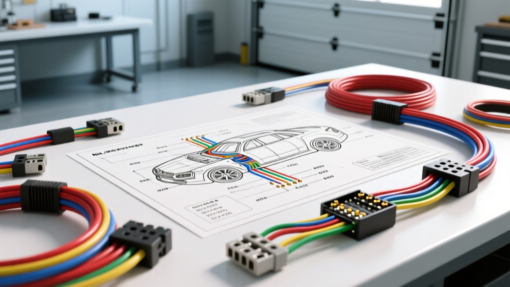
Introduction to NASA Auto Electric Principles
When elite motorsport engineers, land speed racers, and aerospace contractors build extreme expedition vehicles or high-voltage EV conversions, standard automotive wiring practices often fall short. This is where the concept of NASA auto electric integration comes into play. Rather than referring to a specific vehicle brand, "NASA auto electric" defines a methodology: applying rigorous aerospace wiring standards—specifically NASA-STD-8739.4 and IPC/WHMA-A-620—to automotive electrical architectures. By utilizing MIL-SPEC connectors, PTFE-insulated wiring, and redundant shielding, builders achieve zero-failure electrical systems capable of surviving extreme vibration, thermal cycling, and electromagnetic interference (EMI).
In this complete wiring diagram walkthrough, we will dissect a high-reliability 400V EV conversion harness paired with a 12V logic control system. We will cover wire gauge selection, MIL-DTL-26482 circular connector pinouts, pre-charge circuit logic, and single-point grounding topologies. Whether you are wiring a Baja truck or a dual-motor EV swap, these aerospace-grade principles ensure your electrical system will not fail when it matters most.
Stage 1: High-Voltage Traction and Battery Disconnect
The foundation of any high-voltage automotive system is the traction battery and the main contactor circuit. Standard SAE J1128 PVC-insulated wire is inadequate for 400V DC systems due to its low melting point and poor resistance to abrasion. For a NASA-grade build, we specify MIL-W-22759/16 PTFE (Tefzel) insulated wire. For a 250kW motor setup drawing up to 600A peak, we utilize 2/0 AWG XLPE or PTFE cabling.
The main battery disconnect utilizes a Gigavac GV200 series hermetically sealed contactor. The HV+ and HV- cables are terminated with MIL-SPEC compression lugs, torqued to the manufacturer's specification (typically 20 Nm for M8 studs) using Nord-Lock washers to prevent vibrational loosening. The wiring diagram routes the HV+ through a 500A Class T fuse before entering the main inverter, ensuring catastrophic short-circuit protection that standard automotive ANL fuses cannot provide under high DC fault currents.
Stage 2: 12V Logic and Pre-Charge Circuit Pinouts
Closing a main high-voltage contactor directly into an inverter with large DC-link capacitors causes a massive inrush current, which can weld the contactor contacts shut or destroy the capacitors. A pre-charge circuit is mandatory. In our walkthrough, the 12V logic harness utilizes 18 AWG MIL-W-22759/16 wire in a shielded twisted pair configuration to prevent EMI from the HV cables.
The pre-charge circuit consists of a 75-ohm, 50W wire-wound power resistor wired in parallel with the main HV+ contactor. When the ignition switch is turned to the "ON" position, a 12V signal energizes the pre-charge relay first. Current flows through the resistor, safely charging the inverter capacitors to 95% of the pack voltage over approximately 150 milliseconds. A voltage sensor monitors the DC-link; once the threshold is met, the BMS (Battery Management System) energizes the main GV200 contactor and opens the pre-charge relay. This logic sequence is mapped to a Deutsch DTM 12-pin connector at the BMS module.
MIL-SPEC vs. Standard Automotive Wiring Specifications
To understand the value of the NASA auto electric methodology, compare the physical and electrical properties of standard automotive wire against aerospace-grade alternatives.
| Specification | SAE J1128 (Standard Auto) | MIL-W-22759/16 (Aerospace/NASA) |
|---|---|---|
| Insulation Material | PVC or Cross-linked PE | Extruded PTFE (Tefzel) |
| Max Operating Temp | 105°C to 125°C | 150°C to 200°C |
| Dielectric Strength | Moderate (prone to melting) | Extremely High (non-flammable) |
| Weight / Flexibility | Heavier, stiff in cold | Lightweight, high strand count |
| Chemical Resistance | Degrades with oil/fuel | Impervious to automotive fluids |
Stage 3: MIL-DTL-26482 Connectors and Pin Configuration
Standard plastic blade connectors fail under high-vibration conditions due to terminal fretting corrosion. For the main harness bulkhead pass-through, we utilize an Amphenol PT06A-14-19P (MIL-DTL-26482 Series 1) circular connector. This connector features a bayonet locking mechanism, environmental grommets, and gold-plated crimp contacts rated for 7.5A per pin.
Amphenol PT06A-14-19P Pinout Assignment
- Pin 1 & 2: 12V IGN Switched (Red 18 AWG) - Redundant power feed to BMS.
- Pin 3 & 4: Main Contactor Coil Ground (Black 18 AWG) - Low-side driver return.
- Pin 5: CAN-H (Green 22 AWG Shielded) - Inverter communication.
- Pin 6: CAN-L (White 22 AWG Shielded) - Inverter communication.
- Pin 7: HV Interlock Loop + (Orange 20 AWG) - Safety circuit.
- Pin 8: HV Interlock Loop - (Orange 20 AWG) - Safety circuit return.
- Pin 9-12: Spare / Sensor Returns (Shielded).
- Shell: Chassis Ground (Bonded via backshell to braided shield).
The HV Interlock Loop (HVIL) is a critical safety feature. A low-voltage 5V signal is routed through all high-voltage connector backshells in series. If any HV connector is unplugged, the circuit breaks, and the BMS instantly opens the main contactors, de-energizing the HV bus before the pins can physically separate and arc.
EMI Shielding and Single-Point Grounding Architecture
High-frequency switching in motor inverters generates massive electromagnetic interference (EMI), which can corrupt CAN bus signals and cause erratic sensor readings. In a NASA auto electric build, all CAN and low-voltage sensor wires are routed in shielded twisted pairs (STP). The drain wire from the shield must be terminated 360-degrees using a MIL-SPEC backshell with a banding strap, not a pigtail. Pigtailing a shield at high frequencies creates an antenna effect, rendering the shielding useless.
Grounding follows a strict single-point star topology. Instead of daisy-chaining grounds to various chassis bolts (which creates ground loops and voltage offsets), all 12V logic grounds are routed to a central, isolated copper busbar. This busbar is then bonded to the chassis using a single, heavy-duty 4 AWG ground strap, ensuring a common reference potential for all sensitive analog sensors and microcontrollers.
Crimping and Termination Standards
Aerospace standards dictate that a crimp is only as good as its pull-test strength and visual inspection. NASA-STD-8739.4 requires the use of calibrated, indent-style crimp tools (such as the Daniels M22520/2-01 pneumatic crimper) for MIL-SPEC contacts. The crimp must exhibit the correct bellmouth geometry, and the wire strands must be visible in the inspection window of the contact barrel. Heat shrink is applied using a dual-wall, adhesive-lined polyolefin tubing (MIL-I-23053/5) to provide environmental sealing and strain relief, completely eliminating the risk of moisture ingress and capillary action wicking.
Troubleshooting Aerospace-Grade Auto Electrical Faults
When diagnosing a fault in a MIL-SPEC harness, standard multimeter continuity checks are often insufficient for finding intermittent high-resistance faults. Follow this diagnostic tree:
- Symptom: Intermittent CAN Bus Dropouts under Load.
Cause: Shield compromise or ground loop.
Fix: Use an oscilloscope to measure CAN-H and CAN-L differential voltage. If the signal is noisy, inspect the 360-degree backshell terminations. Ensure the shield drain wire is not pigtailed. - Symptom: Pre-Charge Fault Code (Timeout).
Cause: High resistance in the pre-charge resistor or failing relay contacts.
Fix: Measure the resistance of the 75-ohm power resistor. If it reads open or significantly higher, replace it. Check for pitting on the pre-charge relay contacts using a borescope. - Symptom: BMS Fails to Close Main Contactor.
Cause: Broken HVIL (Interlock) loop.
Fix: Perform a Time Domain Reflectometry (TDR) test on the interlock loop to pinpoint the exact distance of the open circuit, or manually probe each connector backshell with a DMM to isolate the broken series link.
Conclusion
Adopting NASA auto electric methodologies transforms a standard vehicle wiring harness into a mission-critical, fail-safe architecture. By upgrading to PTFE wiring, utilizing MIL-DTL circular connectors, enforcing strict pre-charge logic, and adhering to aerospace crimping standards, you eliminate the vast majority of electrical failures that plague high-performance and EV builds. For further reading on aerospace harness fabrication, refer to the latest revisions of NASA-STD-8739.4 and the IPC/WHMA-A-620 acceptance criteria.