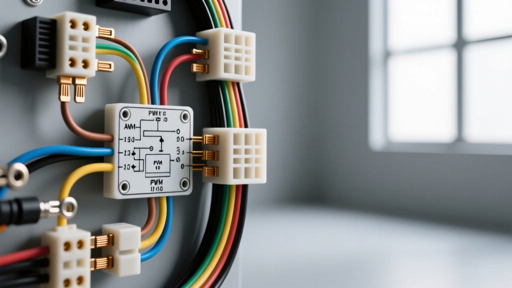
Introduction to Electric Auto AC Systems
The transition from engine-driven to electric auto AC compressors has revolutionized custom vehicle builds, EV conversions, and engine-swap projects. By decoupling the air conditioning compressor from the accessory drive belt, builders gain massive flexibility in engine placement and eliminate parasitic horsepower loss. However, integrating an electric auto AC system requires a rigorous understanding of high-current DC circuits, relay logic, and in modern setups, Pulse Width Modulation (PWM) signaling.
This complete wiring diagram walkthrough breaks down the electrical architecture required to safely and reliably power a 12-volt electric auto AC compressor. Whether you are installing a fixed-speed brushless unit in a classic hot rod or a variable-speed PWM compressor in an EV swap, this guide provides the exact wire gauges, pin configurations, and routing strategies necessary for a factory-quality installation.
Core System Architecture Overview
Before cutting any wire, it is critical to understand the three distinct electrical circuits that govern an electric auto AC system:
- The High-Current Power Feed: Delivers raw 12V+ power from the battery or high-output alternator directly to the compressor motor and heavy-duty contactor.
- The Low-Current Control Circuit: Manages the HVAC thermostat switch, binary/trinary pressure safety switches, and the relay trigger coil.
- The PWM Signal Circuit (Variable-Speed Only):strong> Provides a low-voltage logic signal to the compressor's internal inverter to dictate RPM and cooling capacity.
High-Current Power Feed Walkthrough
Electric auto AC compressors draw significant amperage, particularly during the initial spin-up phase. A typical 12V brushless compressor will pull between 30A and 45A under continuous load, with startup spikes (inrush current) occasionally reaching 60A. Sizing your power and ground wires correctly is non-negotiable to prevent voltage drop, which can cause the compressor's internal inverter to fault or shut down.
Power Wire Routing and Specifications
Run a dedicated 8 AWG primary power wire (typically Red) directly from the positive battery terminal or the main alternator output stud. Do not route this through the ignition switch or a standard fuse box. Instead, install a 60A MAXI fuse or an 80A ANL fuse within 18 inches of the power source. This protects the main power cable in the event of a dead short.
Route the 8 AWG wire to a heavy-duty automotive relay or solid-state contactor mounted in the engine bay, ideally within 3 feet of the compressor to minimize voltage drop on the switched side. Use adhesive-lined marine-grade heat shrink and ratcheting crimpers for all ring terminal connections to prevent corrosion and high-resistance joints.
The Critical Ground Circuit
Many electric auto AC failures are misdiagnosed as bad compressors when they are actually ground-side voltage drops. Do not rely on the compressor's mounting brackets for grounding. Run a dedicated 8 AWG Black ground wire from the compressor's dedicated ground lug directly to the engine block or a clean, bare-metal chassis point. Use a star washer to bite through the paint or powder coat, ensuring a zero-resistance path back to the battery negative terminal.
Control Circuit and Trinary Switch Integration
The control circuit dictates when the high-current relay engages. This circuit is typically wired using 14 AWG or 16 AWG wire and draws less than 2 Amps. The safest and most reliable method to control an electric auto AC compressor is by utilizing a standard Bosch-style ISO mini relay (4-pin or 5-pin) rated for at least 40A continuous duty, or preferably a heavy-duty 80A contactor.
Trinary Pressure Switch Logic
Your control circuit must pass through a trinary pressure switch located on the high-pressure AC line. The trinary switch serves three vital functions:
- Low-Pressure Cutoff (approx. 28 PSI): Prevents the compressor from running if the system is low on refrigerant, which would otherwise destroy the compressor due to lack of lubrication.
- High-Pressure Cutoff (approx. 440 PSI): Prevents catastrophic hose failure or compressor explosion by cutting power if the condenser cannot shed heat fast enough.
- Condenser Fan Trigger (approx. 250 PSI): Engages the electric cooling fan in front of the condenser to maximize heat exchange.
Wire the 12V+ trigger source (from an ignition-switched or HVAC-controller-switched 14 AWG wire) into one side of the trinary switch. The output side of the switch routes to Pin 86 of your heavy-duty relay. Pin 85 of the relay goes to a clean chassis ground.
Variable-Speed PWM Signal Walkthrough
Modern EV conversions often utilize variable-speed electric auto AC compressors (such as Sanden or Denso units). These compressors feature an internal 3-phase inverter and require a PWM signal wire to dictate the compressor's RPM based on cabin cooling demand.
The PWM signal wire is highly susceptible to Electromagnetic Interference (EMI) generated by the high-current switching of the compressor itself and the vehicle's ignition system. You must use a shielded 18 AWG twisted-pair cable for the PWM signal. Connect the signal wire to the HVAC controller's PWM output, and ensure the shield drain wire is grounded at the controller end only to prevent ground loops.
Wiring Specifications and Pinout Reference Tables
Refer to the tables below for exact wire sizing, fusing requirements, and standard relay pinouts when assembling your electric auto AC wiring harness.
| Compressor Type | Max Continuous Draw | Main Power Wire (AWG) | Main Fuse Rating | Control Wire (AWG) |
|---|---|---|---|---|
| 12V Fixed-Speed Brushless | 45 Amps | 8 AWG (Red/Black) | 60A MAXI / 80A ANL | 14 AWG (Light Blue) |
| 12V Variable-Speed (PWM) | 55 Amps | 6 AWG (Red/Black) | 70A ANL | 18 AWG Shielded (Yellow) |
| 24V/48V Heavy-Duty (EV) | 30 Amps | 10 AWG (Red/Black) | 40A MAXI | 16 AWG (Green/White) |
| Pin Number | Function | Connection Target | Wire Color (Typical) |
|---|---|---|---|
| 30 | High-Current Input | From 60A Main Fuse (Battery +) | 8 AWG Red |
| 87 | High-Current Output | To Compressor Positive Terminal | 8 AWG Red |
| 86 | Coil Positive (Trigger) | From Trinary Switch Output | 14 AWG Light Blue |
| 85 | Coil Negative (Ground) | To Clean Chassis Ground | 14 AWG Black |
Real-World Troubleshooting and Failure Modes
Even with a flawless schematic, real-world automotive environments introduce variables that can disrupt your electric auto AC system. Here are the most common failure modes encountered during installation and testing, along with their diagnostic solutions.
Symptom: Compressor Short-Cycles Every 3 to 5 Seconds
Cause: This is almost always a pressure switch issue, but not necessarily due to refrigerant levels. If the condenser fan is wired to the same ground bus as the trinary switch, the voltage drop caused by the fan drawing 15A can trick the trinary switch into reading a false high-pressure or low-pressure state, cutting the circuit.
Fix: Give the condenser fan its own dedicated ground wire routed directly to the chassis. Ensure the trinary switch trigger wire is sourced from a clean, regulated 12V ignition circuit, not a shared accessory bus.
Symptom: Compressor Fails to Start When Engine is Cranking
Cause: Voltage drop during starter engagement. If the compressor's control circuit is wired to a standard ignition run terminal, the voltage drop during cranking (which can dip below 9V) will cause the compressor's internal microcontroller to reset or throw an undervoltage fault code.
Fix: Wire the control circuit trigger through a secondary relay that is energized only when the engine is running (using an oil pressure switch trigger or an ECU-controlled tachometer output relay). Alternatively, install a time-delay relay module that prevents the AC compressor from engaging until 10 seconds after the engine has started.
Symptom: PWM Compressor Runs at 100% RPM and Ignores Thermostat
Cause: Loss of the PWM signal wire or EMI corruption. Most variable-speed electric auto AC compressors are designed with a 'fail-safe' mode: if they lose the PWM logic signal, they default to maximum RPM to ensure the cabin does not overheat and to prevent evaporator core freezing due to lack of airflow modulation.
Fix: Use an oscilloscope to verify the square wave signal at the compressor's 3-pin connector. If the signal is jagged or noisy, reroute the shielded signal wire away from the high-current power cables and ignition coil packs. For deep technical standards on automotive HVAC electrical safety and wiring practices, refer to the SAE J1344 Surface Vehicle Standard and the installation guidelines provided by Vintage Air Technical Bulletins.
Final Verification and Testing
Before charging the system with R134a or R1234yf refrigerant, perform a 'dry run' of the electrical system. Apply 12V directly to the relay trigger coil to ensure the compressor clutch (or brushless motor) engages instantly without hesitation. Use a digital multimeter to measure the voltage drop across the main power wire and the ground wire while the compressor is running; a combined voltage drop exceeding 0.5V indicates undersized wiring or poor terminal crimps. By adhering strictly to these wiring diagram principles, your electric auto AC system will deliver reliable, frosty performance for years to come.