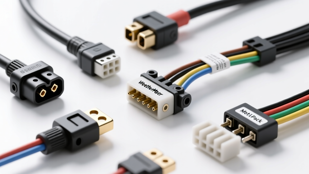
Introduction to Automotive Connector Architectures
When diagnosing complex wiring harness faults or designing custom auxiliary circuits, understanding the specific types of car electrical connectors is critical. Modern vehicle electrical architecture has transitioned away from simple bullet and spade terminals toward highly engineered, environmentally sealed modular systems. These systems must withstand severe under-hood thermal cycling, constant vibration, and exposure to corrosive road salts while maintaining millivolt-level signal integrity for CAN bus networks and high-current delivery for EFI systems.
According to SAE International Standard J2223, automotive electrical connectors are rigorously tested for terminal retention force, vibration resistance, and thermal shock. This technical specification reference details the mechanical dimensions, current ratings, and crimp profiles of the most prevalent connector families used in OEM and aftermarket automotive applications.
Delphi Weather-Pack Series Specifications
Originally developed by Delphi (now Aptiv), the Weather-Pack series remains the industry standard for aftermarket auxiliary lighting, winch controls, and general-purpose sealed automotive circuits. The system utilizes a tower (male) and shroud (female) housing design with individual ribbed silicone seals that slide over the wire insulation to provide a weather-tight barrier.
Terminal Types and AWG Compatibility
Weather-Pack terminals utilize an open-barrel 'F-crimp' design. The terminal features two distinct crimp zones: the conductor crimp (which bites into the bare copper strands) and the insulation crimp (which secures the wire jacket and seal). Proper tooling, such as the Delphi 12094428 equivalent open-barrel crimper, is mandatory to achieve the correct bellmouth crimp profile.
| Seal Color | Wire Gauge (AWG) | Insulation OD (mm) | Max Current Rating |
|---|---|---|---|
| Red | 14 - 16 AWG | 2.40 - 3.30 mm | 20 Amps |
| Blue | 16 - 18 AWG | 1.85 - 2.40 mm | 20 Amps |
| Yellow / Green | 18 - 20 AWG | 1.40 - 1.85 mm | 20 Amps |
| Clear (Cavity Plug) | N/A | N/A | N/A (Sealing only) |
Technical Note: The maximum continuous current rating for a Weather-Pack terminal is 20 Amps. For circuits exceeding this threshold (e.g., starter solenoids or high-amperage cooling fans), you must step up to a larger connector family to prevent thermal runaway and housing melt.
Aptiv Metri-Pack 150, 280, and 630 Series
The Metri-Pack family is the backbone of modern OEM engine management and body control module (BCM) wiring. Unlike Weather-Pack, which uses individual wire seals, Metri-Pack utilizes a single multi-cavity silicone mat seal (or individual loose-piece seals for smaller cavities) that interfaces directly with the terminal blades. The series is categorized by the width of the male terminal blade in millimeters.
Pull-to-Seat vs. Push-to-Seat Mechanics
Metri-Pack terminals are available in two distinct insertion styles. Pull-to-Seat (PTS) terminals are inserted into the housing, and the seal is pulled back over the terminal barbs to lock it in place. Push-to-Seat (often branded as Push-Lock) terminals feature a plastic lock tang that snaps into the housing cavity upon insertion. Identifying the style is crucial, as PTS and Push-Lock housings are not cross-compatible.
| Series | Blade Width | Typical AWG Range | Max Current | Primary OEM Application |
|---|---|---|---|---|
| Metri-Pack 150 | 1.5 mm | 18 - 22 AWG | 14 Amps | ECU Sensors, CAN Bus, Injectors |
| Metri-Pack 280 | 2.8 mm | 14 - 18 AWG | 30 Amps | Relays, Ignition Coils, Solenoids |
| Metri-Pack 480 | 4.8 mm | 10 - 14 AWG | 40 Amps | Blower Motors, ABS Pumps |
| Metri-Pack 630 | 6.3 mm | 8 - 12 AWG | 46 Amps | High-Current Power Feeds, Glow Plugs |
| Metri-Pack 800 | 8.0 mm | 4 - 8 AWG | 80 Amps | Alternator Outputs, Starter Circuits |
For detailed OEM harness integration guidelines, refer to the Aptiv Connection Systems catalog, which outlines the exact Terminal Position Assurance (TPA) lock part numbers required for each cavity count.
TE Connectivity Deutsch DT and DTM Series
When dealing with heavy-duty trucks, off-road equipment, or marine applications, the Deutsch DT series is the undisputed standard. Manufactured by TE Connectivity, these connectors use a thermoplastic housing with an internal wedgelock mechanism that physically locks the terminal in place once inserted, preventing back-out under extreme high-G vibration environments.
Wedgelock and Retention Mechanics
The Deutsch system relies on solid cylindrical pin and socket contacts. The terminal features two crimp barrels (conductor and insulation) and an inspection hole at the front of the conductor barrel to verify full wire insertion before crimping. The wedgelock (a small plastic wedge) must be inserted after the terminals are seated; it spreads the terminal retention barbs outward, locking them behind the housing shelf.
- DT Series: Accepts 14-20 AWG wire. Size 16 contacts rated for 13 Amps continuous.
- DTM Series: A miniature version accepting 20-24 AWG wire. Size 20 contacts rated for 7.5 Amps continuous. Ideal for low-current sensor arrays.
- DTP Series: Heavy-duty variant accepting 10-14 AWG wire. Size 12 contacts rated for 25 Amps continuous.
According to TE Connectivity's Deutsch engineering specifications, the DT series maintains IP68/IP69K sealing integrity even when submerged, provided the rear grommet is fully seated and the optional strain relief boots are installed.
Molex MX150 High-Density Engine Management Connectors
As modern engine control units (ECUs) require upwards of 100+ pins in a single interface, traditional connectors become too bulky. The Molex MX150 system utilizes a 0.60mm x 1.50mm blade terminal, allowing for high-density packaging (up to 24 circuits in a single row). The MX150 features a unique mat-seal design and integrated Terminal Position Assurance (TPA) locks that are pre-assembled into the housing, reducing assembly time and preventing mis-seated terminals during harness manufacturing.
The MX150 is heavily used in modern direct-injection fuel systems, transmission control modules (TCMs), and electronic throttle bodies. Because the terminal mass is small, heat dissipation is limited; therefore, the MX150 is generally capped at 14 Amps for 18 AWG wire and 18 Amps for 16 AWG wire.
Troubleshooting Fretting Corrosion and Terminal Tension
Understanding the types of car electrical connectors is only half the battle; diagnosing their failure modes is where master technicians separate themselves from parts-swappers. The most common failure in sealed automotive connectors is fretting corrosion.
The Mechanics of Fretting Corrosion
Fretting occurs when engine vibration causes microscopic movements (as small as 10 microns) between the male and female terminal contact points. If the terminals are tin-plated (standard for most non-signal circuits), this micro-movement wears away the tin oxide layer, exposing raw tin to oxygen, which immediately re-oxidizes. Over thousands of thermal and vibrational cycles, this builds up a high-resistance insulating layer of tin oxide, leading to voltage drops, sensor ghosting, and misfires.
Diagnostic and Remediation Protocol
- Measure Voltage Drop: Do not rely on continuity tests. A multimeter will often read 0.0 ohms across a fretted terminal because the test leads do not apply enough mechanical force to break through the oxide layer. Perform a dynamic voltage drop test across the connector while the circuit is under load (target: < 100mV).
- Inspect Terminal Tension: Use a calibrated pin drag test. A female terminal should exhibit noticeable mechanical resistance when a standard test pin is inserted and withdrawn. If the terminal feels 'loose', the internal beryllium-copper spring tang has yielded and the terminal must be replaced.
- Apply Dielectric Compounds: To prevent fretting on tin-plated terminals, apply a specialized dielectric grease (such as Nyogel 760G or Stabilant 22) during assembly. These compounds contain microscopic conductive particles or high-viscosity bases that exclude oxygen and dampen micro-vibrations without increasing overall circuit resistance.
- Upgrade Plating for Signals: For low-voltage analog sensors (e.g., O2 sensors, MAF sensors), ensure you are using silver or gold-plated terminals, which do not form insulating oxide layers and are highly resistant to fretting corrosion.
By matching the correct connector architecture to the specific current, environmental, and vibrational demands of the circuit, you ensure long-term electrical reliability and eliminate the most common causes of parasitic voltage loss in automotive systems.