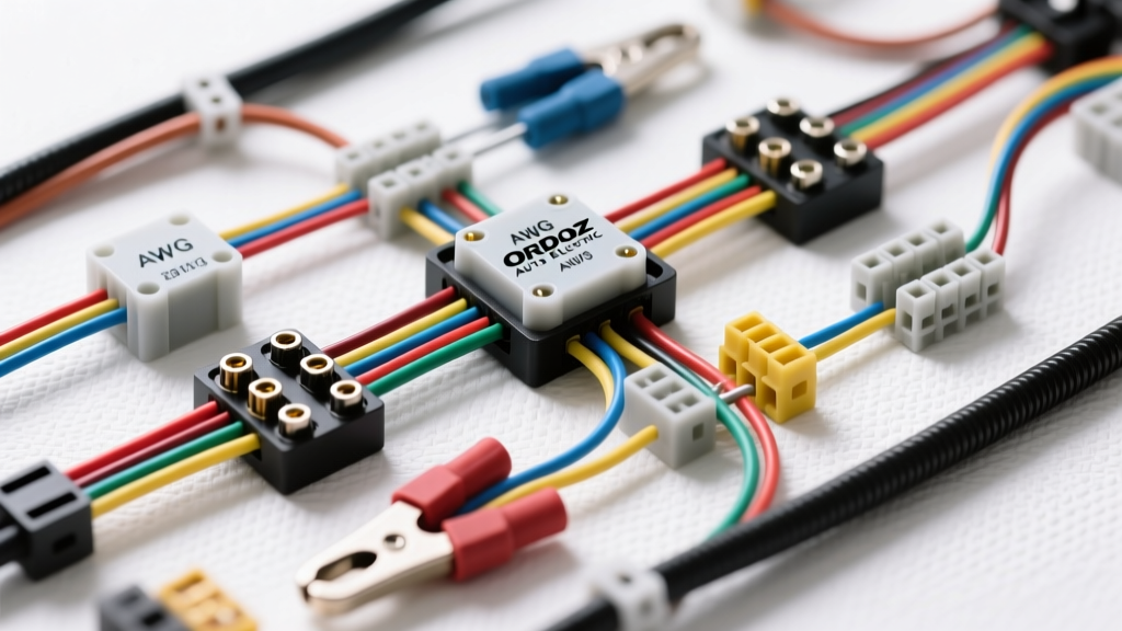
Introduction to Custom Harness Architecture
When building or restoring a vehicle, the electrical architecture is the central nervous system of the machine. The Ordaz Auto Electric wiring diagram methodology has become a benchmark in custom chassis wiring, street rod builds, and classic car restorations. Unlike factory harnesses that rely on daisy-chained grounds and undersized multiplexed circuits, a proper custom harness walkthrough emphasizes circuit segregation, centralized grounding, and heavy-duty power distribution. This comprehensive guide walks through the core tenets of the Ordaz Auto Electric diagram standard, detailing wire gauges, routing strategies, and relay configurations required for a bulletproof automotive electrical system.
Before routing a single wire, it is critical to select the correct insulation type. Following SAE J1128 standards for low-tension primary cable, custom harnesses should exclusively use GXL (General Cross-Linked) or TXL (Thin-wall Cross-Linked) wire. These insulations resist high under-hood temperatures (up to 125°C continuous) and allow for tighter bend radii without compromising the dielectric barrier, unlike standard PVC wire which becomes brittle and melts near exhaust headers.
Decoding the Ordaz Auto Electric Main Fuse Block
The heart of this wiring diagram walkthrough is the centralized fuse block. Rather than scattering fuses throughout the cabin and engine bay, the Ordaz methodology utilizes a single, high-capacity marine-grade fuse block with an integrated negative busbar. Below is the standard circuit allocation and wire specification chart for the primary 12-cavity distribution block.
| Cavity | Circuit Name | Wire Color Code | AWG Size | Max Fuse Rating |
|---|---|---|---|---|
| 01 | Headlights (High Beam) | Blue w/ White Stripe | 12 AWG | 15A |
| 02 | Headlights (Low Beam) | Blue | 12 AWG | 15A |
| 03 | Electric Cooling Fan 1 | Dark Green | 10 AWG | 30A |
| 04 | Electric Fuel Pump | Purple | 12 AWG | 15A |
| 05 | Ignition Switch (Run/Start) | Red w/ White Stripe | 10 AWG | 20A |
| 06 | Instrument Cluster & Gauges | Gray | 14 AWG | 10A |
| 07 | Turn Signals & Hazards | Light Green | 14 AWG | 15A |
| 08 | Wipers & Washer Motor | Black w/ Pink Stripe | 14 AWG | 15A |
| 09 | Horn Relay Trigger | Yellow | 16 AWG | 5A |
| 10 | ECU / EFI Main Power | Orange | 10 AWG | 25A |
| 11 | Interior Dome & Courtesy | White | 14 AWG | 10A |
| 12 | Accessory / Cigarette Lighter | Brown | 12 AWG | 20A |
By strictly adhering to these color codes and AWG ratings, technicians can rapidly trace faults using a multimeter without needing to constantly reference the schematic. Note that high-draw components like cooling fans and fuel pumps utilize 10 AWG or 12 AWG wire, even if the component only draws 12 amps continuously. This oversizing mitigates voltage drop over long chassis runs, a core principle highlighted in AutoShop 101 electrical fundamentals.
Headlight and Front Accessory Circuit Walkthrough
Factory headlight circuits often route full amperage through the steering column switch, leading to melted connectors and dim halogen output. The Ordaz Auto Electric diagram eliminates this by using the column switch merely as a low-amperage trigger for under-hood Bosch-style ISO mini relays.
ISO Relay Pinout Configuration
For the headlight circuits, standard 5-pin SPDT (Single Pole Double Throw) relays are deployed in the engine bay, within 3 feet of the headlight buckets. The wiring is configured as follows:
- Pin 30 (Power In): 10 AWG Red wire directly from the battery positive terminal via a 30A maxi-fuse.
- Pin 87 (Power Out - Normally Open): 12 AWG Blue wire routing to the headlight positive terminal.
- Pin 85 (Relay Ground): 14 AWG Black wire terminating at the nearest dedicated chassis ground stud.
- Pin 86 (Trigger In): 16 AWG Blue/White wire running back to the steering column dimmer switch.
- Pin 87a (Power Out - Normally Closed): Unused and insulated in this specific headlight application.
This setup ensures that the heavy current (12-15 amps) only travels a short distance from the battery to the relay, and from the relay to the bulb. The steering column switch only carries the relay coil draw (approximately 0.2 amps), drastically extending the life of the vintage switchgear.
Ignition, Starter, and Alternator Routing
The charging and starting circuits are where many custom builds fail due to improper wire sizing and poor routing. The Ordaz methodology dictates a dedicated 4 AWG charge wire from the alternator output stud to the starter solenoid battery post, bypassing the ammeter entirely to prevent fire hazards associated with high-amperage cabin routing.
3-Wire Alternator Exciter and Sense Circuit
For builds utilizing a classic 10SI, 12SI, or CS130D 3-wire alternator, the diagram mandates proper excitation and voltage sensing. A 1-wire alternator setup is discouraged for vehicles with high electrical loads (EFI, electric fans, MSD ignition) because it requires high RPMs to 'turn on' the regulator and senses voltage locally at the alternator, not at the battery.
- Pin 1 (L - Lamp/Exciter): A 16 AWG Brown wire routed through the dash indicator bulb (or a 10-ohm 2-watt resistor in parallel) to a switched 12V ignition source. This provides the initial voltage spike required to excite the alternator's rotor field upon startup.
- Pin 2 (S - Sense): A 14 AWG Red wire that must be routed directly to the positive battery post or the main distribution busbar. Tying the sense wire to the alternator output stud defeats the purpose of a 3-wire system, as it will not compensate for voltage drop across the main charge cable.
For the starter solenoid trigger, a 12 AWG Purple wire is routed from the ignition switch 'Start' terminal, through a neutral safety switch (for automatics) or clutch interlock switch (for manuals), down to the 'S' terminal on the starter solenoid. To prevent 'run-on' or back-feeding from the starter's 'I' (Ignition) bypass terminal, a diode is installed in-line on the Purple trigger wire, ensuring current flows only toward the solenoid.
Grounding Strategy and Chassis Returns
A wiring diagram is only as effective as its return paths. The Ordaz Auto Electric standard strictly forbids 'daisy-chain' grounding, where multiple components ground to a single sheet metal screw. Instead, a centralized ground busbar system is employed.
All ground wires (Black) from the engine bay harness terminate at a heavy-duty, tinned copper busbar mounted to the inner fender. This busbar is then tied to the engine block and the chassis frame using minimum 6 AWG braided copper ground straps. When attaching ground straps to the chassis or engine block, the paint, powder coat, or rust must be aggressively removed using a wire wheel or sanding disc to ensure bare metal-to-metal contact. A conductive anti-corrosion compound (like Noalox) is applied over the terminal after torquing to prevent oxidation, which acts as a semiconductor and causes erratic sensor readings in modern EFI systems.
Troubleshooting Custom Harness Voltage Drops
Even with a flawless Ordaz Auto Electric diagram execution, physical degradation or poor crimping can introduce resistance. According to Haynes Automotive Wiring guidelines, voltage drop testing is the only accurate method to find hidden resistance without piercing wire insulation.
Millivolt Drop Thresholds
Set your digital multimeter to DC millivolts (mV). Place the red probe on the battery positive post and the black probe on the component's positive terminal while the circuit is under load.
- 10 AWG to 4 AWG High-Amp Circuits (Starters, Alternators): Maximum allowable drop is 0.20V (200mV).
- 12 AWG to 14 AWG Low-Amp Circuits (Lights, Sensors): Maximum allowable drop is 0.10V (100mV).
- Computer/ECU Ground Returns: Maximum allowable drop is 0.05V (50mV). Anything higher will skew 5V reference signals and oxygen sensor readings.
If the voltage drop exceeds these parameters, inspect the crimp terminals. Open-barrel crimps (using a ratcheting crimper) are mandatory; soldering alone is prohibited in high-vibration automotive environments because solder wicks into the wire strands, creating a rigid point that will eventually fatigue and snap under engine harmonics.
Summary
Executing a complete wiring diagram walkthrough based on the Ordaz Auto Electric principles transforms a chaotic bundle of wires into a reliable, serviceable, and safe electrical architecture. By utilizing GXL wire, ISO relay integration, 3-wire alternator sensing, and centralized busbar grounding, you ensure the vehicle's electrical system can handle modern accessory loads while maintaining the reliability required for the open road.