Prerequisites and Safety Protocols
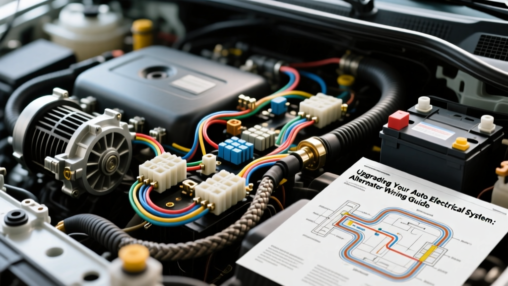
Upgrading the main charging circuit is the most critical modification you can make when expanding the capacity of your auto electrical system. Whether you are installing a 220A Denso-style hairpin alternator for a high-wattage car audio setup, or a 160A GM DR44G replacement for heavy auxiliary lighting, the factory wiring will bottleneck your performance and create a severe fire hazard. According to Hella's automotive electrical technical guidelines, an alternator operating at maximum output through undersized wiring will experience massive voltage drop, leading to premature diode bridge failure and melted insulation.
CRITICAL SAFETY WARNING: Always disconnect the negative battery terminal first, and the positive terminal second. Use insulated tools rated for at least 1000V. Never route high-amperage 12V+ cables parallel to low-voltage ECU sensor harnesses to prevent electromagnetic interference (EMI).Understanding the Auto Electrical System Bottleneck
Most factory vehicles utilize 8 AWG or 6 AWG wiring for the main B+ charging circuit, often protected by a slow-blow fusible link. While sufficient for a stock 105A alternator, pushing 200+ amps through 8 AWG wire violates the ampacity limits defined in SAE J1128 standards for low-tension primary cables. The resistance in the undersized wire generates heat (P = I²R), which increases resistance further, creating a thermal runaway scenario that starves the battery of voltage and forces the alternator's internal voltage regulator to work at a 100% duty cycle.
Factory Wire Gauge vs. High-Output Requirements
Original equipment manufacturers (OEMs) use specific color codes for charging wires. For example, GM trucks typically use a 6 AWG Red wire with a White stripe for the main B+ output, and a 10 AWG Red/White stripe wire for the remote voltage sense circuit. Ford often uses a Black wire with an Orange stripe. When upgrading your auto electrical system, you must bypass or completely replace these factory circuits with pure Oxygen-Free Copper (OFC). Never use Copper-Clad Aluminum (CCA) wire, as it possesses 30% higher resistance and is highly susceptible to galvanic corrosion at the crimp terminals.
AWG Cable Sizing Chart for Alternator Upgrades
| Max Alternator Output | Recommended AWG (OFC) | Max Run Length (One Way) | Required Overcurrent Protection |
|---|---|---|---|
| Up to 150A | 4 AWG | 8 Feet | 175A ANL / Mega Fuse |
| 151A - 225A | 1/0 AWG | 10 Feet | 250A ANL / Mega Fuse |
| 226A - 300A | 2/0 AWG | 12 Feet | 350A ANL / Mega Fuse |
| 301A - 400A+ | 4/0 AWG | 15 Feet | 500A ANL Fuse |
Note: Fuse sizing is calculated at 125% of the maximum continuous alternator output to prevent nuisance blowing during transient voltage spikes while still protecting the cable from short-circuit thermal events.
Step-by-Step Installation: The Big Three Wiring Upgrade
To properly integrate a high-output alternator into your auto electrical system, you must perform the 'Big Three' upgrade: Alternator B+ to Battery Positive, Engine Block to Chassis, and Battery Negative to Chassis.
Step 1: Fabricating the B+ Charging Cable
- Measure and Cut: Measure the distance from the alternator B+ post to the battery positive terminal. Add 6 inches for slack and routing. Cut your 1/0 AWG OFC cable using heavy-duty ratcheting wire cutters to ensure a perfectly square edge.
- Strip and Prep: Strip 5/8 inch of insulation. Use a brass wire brush to lightly clean the exposed copper strands to remove any surface oxidation. Apply a small amount of dielectric grease or antioxidant compound (like Noalox) inside the terminal barrel to prevent future galvanic corrosion.
- Crimping: Insert the wire into a 1/0 AWG to 3/8-inch (M10) closed-end, adhesive-lined marine heat shrink ring terminal. Use a calibrated hex-crimp tool (not an indentor crimper). A hex crimp applies uniform radial pressure, achieving a cold-weld gas-tight connection that meets Battery Council International (BCI) vibration and pull-test standards.
- Seal the Connection: Apply heat with a heat gun (not an open flame) until the adhesive lining purges slightly from the terminal barrel, ensuring a waterproof seal.
Step 2: Installing Overcurrent Protection
Per ABYC and SAE best practices, the main overcurrent protection device must be installed within 7 inches of the battery positive terminal. Install an ANL fuse holder on the firewall or inner fender well. Route the 1/0 AWG cable from the alternator to the load side of the ANL fuse, and use a short jumper cable from the line side of the fuse to the battery positive post. Ensure the fuse holder is mounted in a dry location away from exhaust headers.
Step 3: Alternator B+ Connection and Torque
Remove the factory OEM charging wire from the alternator B+ stud. Cap the factory wire with a sealed heat-shrink cap and zip-tie it to the harness—do not cut it, in case you ever need to revert to stock. Slide your new 3/8-inch ring terminal over the M10 B+ stud. Install the factory washer and a new M10 x 1.25 flange nut. Torque to exactly 15 Nm (11 lb-ft). Overtorquing can strip the soft copper stud or crack the internal rectifier plate.
Step 4: Upgrading the Engine-to-Chassis Ground
The alternator grounds through its aluminum casing to the engine block, and then through the factory ground strap to the chassis. Factory braided straps often corro internally. Fabricate a 1/0 AWG ground cable with 3/8-inch ring terminals. Connect one end to a clean, bare-metal mounting bolt on the engine block (such as the alternator bracket mounting bolt) and the other end to a dedicated chassis ground point. Use a wire wheel to strip away all paint, powder coat, and rust from the mating surfaces to ensure bare metal-to-metal contact.
Step 5: Upgrading the Battery-to-Chassis Ground
Run a second 1/0 AWG ground cable from the battery negative terminal to the vehicle's main chassis ground point (usually located on the frame rail near the engine bay firewall). Apply a coat of clear nail polish or electrical contact protectant over the bare metal mating surface after torquing to prevent future oxidation.
Terminal, Hardware, and Torque Specifications
| Connection Point | Hardware Size | Terminal Type | Torque Specification |
|---|---|---|---|
| Alternator B+ Post | M10 x 1.25 Flange Nut | 3/8' (M10) Ring | 15 Nm (11 lb-ft) |
| ANL Fuse Holder Stud | 5/16' or 3/8' Hex Nut | Matched Ring | 10 Nm (7.5 lb-ft) |
| Battery Side Post (GM) | M8 x 1.25 Bolt | Specialty Side-Post Ring | 11 Nm (8 lb-ft) |
| Battery Top Post | Lead Clamp / Military Terminal | 3/8' Top Post Adapter | Hand Tight + 1/4 Turn |
| Engine Block Ground | M10 or 3/8' Grade 8 Bolt | 3/8' (M10) Ring | 35 Nm (26 lb-ft) |
Testing and Validation: Voltage Drop Testing
Once the physical installation of your upgraded auto electrical system is complete, you must validate the integrity of the connections using a Digital Multimeter (DMM). A resistance check (Ohms) is insufficient for high-current circuits because a single strand of copper can show 0.01 Ohms but will instantly melt under 200A of load.
Performing the Dynamic Voltage Drop Test
- Set your DMM to DC Volts (20V scale).
- Start the vehicle and turn on all major electrical loads (headlights on high beam, HVAC blower on max, rear defroster, and heated seats) to force the alternator into maximum output.
- Place the red DMM probe directly on the alternator B+ nut (not the cable).
- Place the black DMM probe directly on the battery positive post.
- Read the voltage. A healthy, properly crimped 1/0 AWG circuit should show a voltage drop of 0.10V or less. If your reading is 0.25V or higher, you have a high-resistance fault (likely a poor crimp or corroded mating surface) that must be addressed immediately.
- Repeat the test for the ground side: Place the red probe on the alternator casing and the black probe on the battery negative post. The ground side voltage drop should also be 0.10V or less.
By adhering to these rigorous installation protocols, utilizing proper OFC cabling, and validating with dynamic voltage drop testing, you ensure that your auto electrical system will reliably deliver maximum amperage without thermal degradation, securing the longevity of your alternator, battery, and sensitive onboard ECUs.