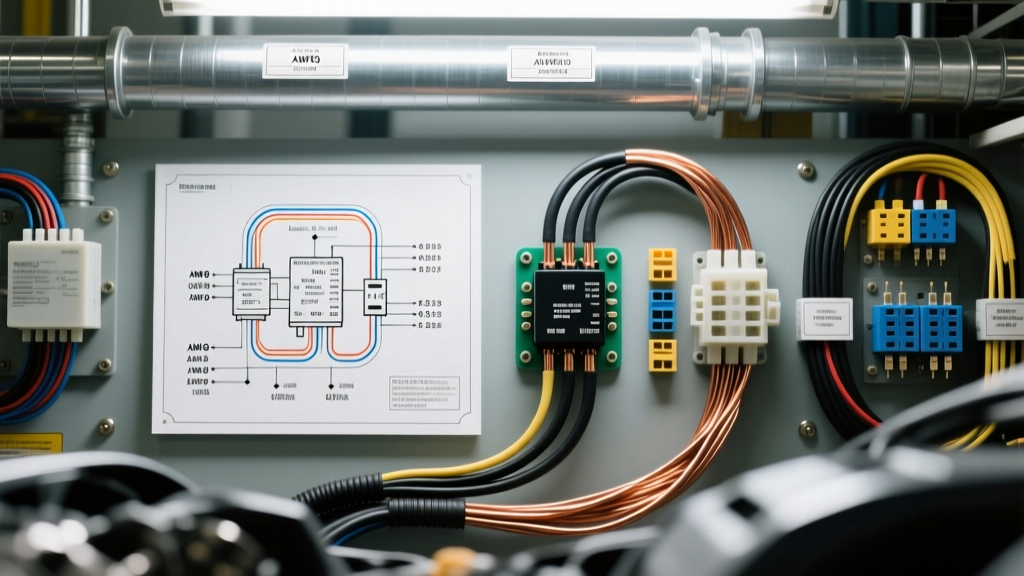
The 'Patrick's Auto Electric' Philosophy: Doing It Right Once
When veteran mechanics, hot-rodders, and restoration specialists discuss the gold standard of automotive electrical work, they often invoke the meticulous, no-nonsense practices of legendary master shops like Patrick's Auto Electric. The 'Patrick's approach' is not about taking shortcuts or using the cheapest materials from the local hardware store. It is about understanding the fundamental physics of a 12-volt DC system, respecting electron flow, and building harnesses that will outlast the vehicle itself. For beginners stepping into the world of automotive electrical diagnostics and custom wiring, adopting these foundational principles is the difference between a reliable daily driver and a rolling fire hazard.
This guide breaks down the core tenets of beginner-friendly automotive wiring, translating old-school master technician wisdom into actionable, modern standards. We will cover wire selection, circuit architecture, relay logic, and the ultimate diagnostic tool: voltage drop testing.
The Anatomy of a Reliable 12V Automotive Circuit
Every functioning electrical circuit in a vehicle, from a simple dome light to a complex EFI fuel pump, relies on a continuous, unbroken loop. According to the foundational training used by top-tier auto electricians, a proper circuit must contain four distinct elements, executed in a specific order:
- Power Source: Typically the battery positive terminal or a fused distribution block tied directly to the battery.
- Overcurrent Protection: A fuse or circuit breaker placed as close to the power source as physically possible (within 7 inches per SAE and ABYC guidelines) to protect the wire, not just the component.
- Control Mechanism: A switch, relay, or solid-state module that interrupts or allows current flow to the load.
- The Load & Ground: The component doing the work (bulb, motor, solenoid), followed by a low-resistance path back to the battery negative terminal via the vehicle chassis or a dedicated ground wire.
A common beginner mistake is placing the fuse after the switch or near the load. If the wire between the battery and the fuse chafes against a sharp firewall edge, it will short to ground and melt, bypassing the fuse entirely. Always protect the wire from the source.
Wire Selection: SAE Standards and the CCA Trap
Master electricians strictly adhere to the SAE J1128 standard for automotive wiring. This standard dictates the use of high-strand-count, pure copper wire with cross-linked polyethylene (XLPE) insulation, commonly known as GXL, TXL, or SXL wire. These insulations resist under-hood heat, automotive fluids, and abrasion far better than standard PVC wire.
The CCA Warning: Beginners must avoid Copper-Clad Aluminum (CCA) wire at all costs. CCA wire is cheaper and lighter, but aluminum has roughly 60% higher electrical resistance than pure copper. This means a 12 AWG CCA wire will experience the same voltage drop and heat generation as a 14 AWG pure copper wire. Furthermore, when CCA wire is exposed to moisture at the crimp joint, galvanic corrosion occurs rapidly, leading to brittle, high-resistance connections that fail under load.
Automotive Wire Gauge (AWG) Sizing Chart
Sizing wire correctly requires calculating the amperage draw of the load and the length of the wire run. The chart below reflects pure copper wire capacities for standard 12V chassis wiring (runs under 15 feet). Always match the fuse to the wire's ampacity, not the load's draw.
| AWG Size | Max Ampacity (Chassis) | Typical Application | Max Fuse Size |
|---|---|---|---|
| 18 AWG | 6 Amps | Dash LEDs, ECU sensor signals, low-draw relays | 5A or 7.5A |
| 16 AWG | 10 Amps | Interior lighting, radio memory, horn triggers | 10A |
| 14 AWG | 15 Amps | Headlights (H4 low beam), power windows, fuel pumps | 15A |
| 12 AWG | 20 Amps | Power seats, rear window defrosters, auxiliary lights | 20A |
| 10 AWG | 30 Amps | High-amperage cooling fans, ABS modules, main feeds | 30A |
| 8 AWG | 45 Amps | Alternator main output, starter solenoid feeds, inverters | 40A or 50A |
Mastering the Bosch-Style 5-Pin Relay
The 5-pin ISO mini relay (often referred to as a Bosch-style relay) is the workhorse of automotive electrical systems. It allows a low-amperage switch (like a dashboard toggle or an ECU output) to safely control a high-amperage load (like a bank of off-road LEDs or a starter solenoid) without routing heavy-gauge wire through the vehicle's cabin.
Understanding the DIN 72552 terminal numbering system is mandatory for any aspiring auto electrician. Miswiring a relay can result in back-feeding voltage into sensitive ECU circuits or blowing control-side fuses instantly.
Standard 5-Pin Relay Pinout & Wiring Guide
| Pin Number | Function | Typical Wire Color | Recommended AWG |
|---|---|---|---|
| 30 | Common Input (12V+ from Battery/Fuse) | Red or Black (Heavy) | 12 AWG - 10 AWG |
| 87 | Normally Open (NO) Output to Load | Red or Blue | 12 AWG - 10 AWG |
| 85 | Coil Ground (or Trigger, depending on setup) | Black | 16 AWG - 18 AWG |
| 86 | Coil 12V+ Trigger (from Switch/ECU) | White or Yellow | 16 AWG - 18 AWG |
| 87a | Normally Closed (NC) Output (Unused in most basic setups) | N/A (Tape and secure) | N/A |
Pro-Tip from the Bench: When wiring Pin 85 and 86 (the electromagnetic coil), polarity technically does not matter for the relay to click. However, if the relay contains an internal suppression diode (to prevent voltage spikes from frying your ECU), wiring the coil backward will blow the internal diode and destroy the relay. Always check the schematic printed on the relay casing.
Termination: The Make-or-Break Connection
The majority of automotive electrical failures do not occur in the middle of a wire; they occur at the termination points. The 'Patrick's Auto Electric' methodology strictly forbids the use of cheap, non-ratcheting crimpers and uninsulated vinyl terminals for critical circuits.
- Open Barrel vs. Closed Barrel: For custom harness building, open-barrel crimping (using a Deutsch-style or Ultra-Terminal crimper) provides a superior, gas-tight mechanical bond. The crimper folds the metal wings over the bare wire strands, creating a cold-weld effect.
- Adhesive-Lined Heat Shrink: Always use dual-wall, adhesive-lined heat shrink terminals. When heated, the inner layer of thermoplastic adhesive melts and flows into the wire strands, creating a waterproof seal that prevents capillary action from wicking moisture under the insulation.
- Ground Studs: When terminating a ground wire to the chassis, use a ring terminal (never a spade/fork terminal, which can vibrate loose). The mounting surface must be stripped to bare, shiny metal. Use a star washer under the ring terminal to bite into the metal, and torque an M8 ground stud to 15-20 Nm to ensure a permanent, low-resistance path.
The Ultimate Diagnostic: Voltage Drop Testing
Beginners often rely on test lights or multimeter continuity checks to diagnose wiring faults. Master technicians know these tools are insufficient for 12V automotive systems. A single strand of copper wire can show 'continuity' on a multimeter but will instantly fail when asked to carry 20 amps to a cooling fan. The only true test of a circuit's health is a voltage drop test under load.
As detailed in comprehensive Painless Performance wiring manuals and SAE diagnostic procedures, voltage drop testing measures the exact amount of electrical pressure (voltage) lost as current pushes through resistance in wires, connectors, and switches.
How to Perform a Voltage Drop Test
- Set your digital multimeter (DMM) to DC Volts.
- Turn the circuit ON so current is flowing (the load must be active).
- Place the red probe on the battery positive terminal and the black probe on the load side of the component you are testing (e.g., the input side of a headlight bulb).
- Read the display. You are measuring the difference in potential between two points.
The Golden Rules of Voltage Drop:
- Across a wire or fuse: Should be less than 0.05V.
- Across a switch or relay contact: Should be less than 0.10V.
- Across the entire ground path (Load case to Battery Negative): Should be less than 0.10V to 0.20V maximum.
If your DMM reads 1.5V across a headlight ground wire, that wire is acting as a resistor. It is generating heat, and the headlight is only receiving 10.5V instead of 12V, resulting in a dim bulb. The fix is not a higher wattage bulb; the fix is cleaning the ground, upgrading the AWG, or repairing a corroded crimp.
Conclusion: Building for the Long Haul
Adopting the rigorous standards championed by legendary shops like Patrick's Auto Electric transforms a beginner from a 'parts swapper' into a true automotive electrical technician. By respecting SAE wire standards, avoiding CCA traps, mastering DIN relay logic, and utilizing voltage drop testing, you ensure that every harness you build or repair is safe, efficient, and built to endure the harsh vibrational and thermal environment of the modern automobile. Invest in quality crimpers, use pure copper GXL wire, and always test under load.