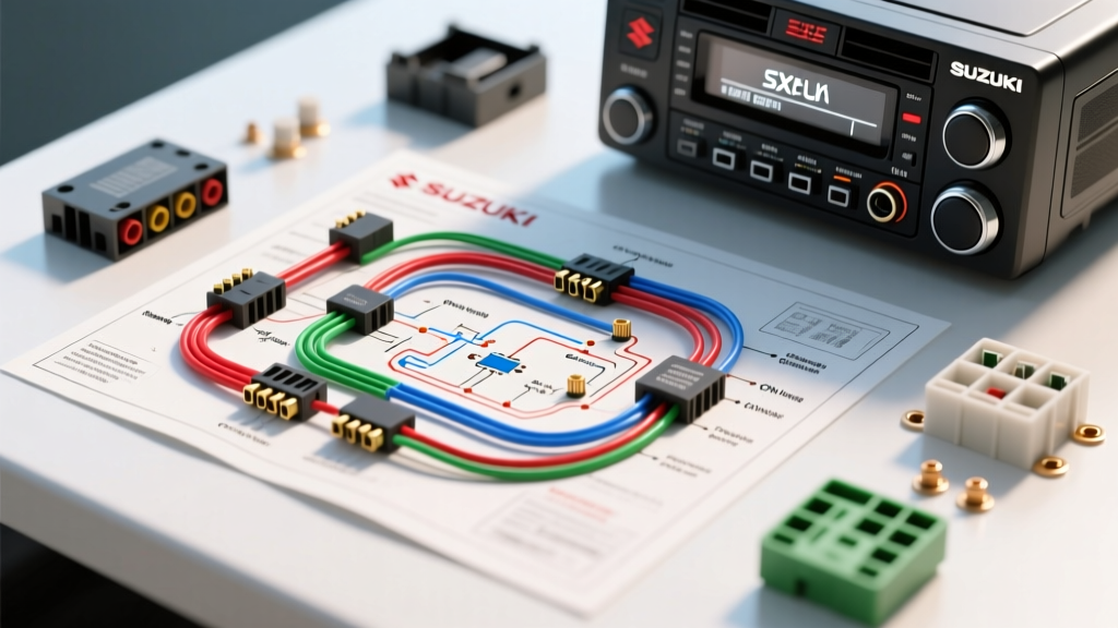
Understanding the Suzuki SX4 Head Unit Architecture
Troubleshooting the factory or aftermarket stereo in a Suzuki SX4 (2006–2014) requires a methodical approach to its unique electrical architecture. Unlike standard ISO DIN setups, the SX4 utilizes a proprietary multi-pin harness configuration that integrates power, speaker outputs, illumination, and a resistor-based Steering Wheel Control (SWC) network. When diagnosing electrical faults, relying on a generic wiring guide often leads to misdiagnosed grounds or shorted data lines. This comprehensive Suzuki SX4 radio wiring diagram troubleshooting flow is designed for automotive electrical technicians and advanced DIYers to isolate faults from the fuse panel to the head unit connector.
Before beginning any diagnostic flow, disconnect the negative battery terminal to prevent accidental shorting of the CAN-bus or multiplex communication lines. When testing live circuits, always use a high-impedance digital multimeter (DMM) rather than a test light, as test lights can draw enough current to trigger fault codes in the Suzuki Body Control Module (BCM). For deeper electrical schematics and factory grounding points, cross-reference your findings with the Haynes Suzuki SX4 Repair Manuals or the Crutchfield Suzuki SX4 Fit Guide for aftermarket harness adapter mappings.
Master Suzuki SX4 Radio Wiring Diagram Pinout Reference
The standard SX4 head unit connects via two primary harnesses: a 20-pin power/data connector and a 16-pin speaker connector. Note that OEM wire colors can vary slightly by manufacturing month and market (e.g., JDM vs. North American spec). Always verify with a DMM.
| Connector / Pin | Wire Color (Typical NA Spec) | Function | AWG / Notes |
|---|---|---|---|
| 20-Pin / Pin 1 | Red/White or Yellow | Constant 12V (Battery) | 18 AWG (Memory/Keep-Alive) |
| 20-Pin / Pin 2 | Blue/White or Blue | Switched 12V (Ignition ACC) | 18 AWG (Wake-up Signal) |
| 20-Pin / Pin 3 | Black | Chassis Ground | 16 AWG (Main Return Path) |
| 20-Pin / Pin 4 | Red/Blue | Illumination (Dimmer) | 20 AWG (Dash Lighting) |
| 20-Pin / Pin 5 | Blue/White Stripe | Power Antenna / Amp Turn-On | 18 AWG (Max 300mA draw) |
| 20-Pin / Pin 14 | Blue/Yellow | Steering Wheel Control (SWC) | 20 AWG (Resistor Ladder) |
| 16-Pin / Pins 1-8 | White, Gray, Green, Purple | Front/Rear Speaker (+) Outputs | 20 AWG (OEM 15W RMS max) |
| 16-Pin / Pins 9-16 | Color w/ Black Stripe | Front/Rear Speaker (-) Returns | 20 AWG (Do NOT ground to chassis) |
Step-by-Step Diagnostic Troubleshooting Flow
Follow the decision trees below based on your primary symptom. Do not skip steps, as modern automotive electrical systems often mask root causes behind secondary BCM protections.
Fault Path 1: Complete Loss of Power (Dead Unit)
Symptom: The head unit display is blank, no audio is present, and the unit does not respond to the volume knob or eject button.
- Step 1: Verify Fuse Integrity. Locate the interior fuse panel (driver’s side kick panel). Check the RADIO (10A) and IG1 (15A) fuses. Use a multimeter in continuity mode; do not rely on visual inspection, as hairline cracks can be invisible.
- Step 2: Back-Probe the 20-Pin Connector. Reconnect the battery. Set your DMM to DC Voltage. Back-probe Pin 1 (Constant 12V) and Pin 3 (Ground) with the ignition OFF. You should read 12.2V–12.6V. If 0V, trace the constant wire back to the fusible link block in the engine bay.
- Step 3: Test the ACC Wake-Up Signal. Turn the key to the ACC position. Back-probe Pin 2 (Switched 12V). If voltage is absent, check the ignition switch wiring harness behind the steering column for worn contacts, a common failure point in high-mileage SX4s.
- Step 4: Verify Chassis Ground. The OEM ground ring terminal is bolted to the lower steering column support bracket (10mm hex bolt). Remove the bolt, clean the mating surface with a wire brush to bare metal, and re-torque to 8 Nm. A poor ground will prevent the internal switching power supply of the head unit from initializing.
Fault Path 2: Intermittent Audio & Ground Loop Noise
Symptom: Alternator whine that pitches with engine RPM, or audio cutting out when driving over bumps.
- Step 1: Isolate Speaker Returns. A common aftermarket installation error is grounding the speaker negative wires (Pins 9-16 on the 16-pin harness) to the vehicle chassis. The SX4 uses a BTL (Bridge-Tied Load) amplifier IC inside the head unit. Grounding a BTL output will cause thermal shutdown or blow the internal IC. Verify all speaker negative wires are floating and isolated from chassis ground.
- Step 2: Check for Alternator Whine. If a high-pitched whine is present, measure the AC voltage ripple on Pin 1 (Constant 12V) while the engine is running. According to SAE J1113 Electromagnetic Compatibility Standards, automotive audio circuits should exhibit less than 50mV of AC ripple. If ripple exceeds this, the vehicle's alternator diode pack is failing, or the head unit's internal filtering capacitors have dried out.
- Step 3: Inspect the Door Jamb Boots. If only one speaker cuts out over bumps, the issue is rarely the head unit. Inspect the rubber wiring boots between the front doors and the A-pillars. The 20 AWG speaker wires are prone to fatigue and breaking at the hinge point due to repeated door articulation.
Fault Path 3: Parasitic Battery Drain (Accessory Wire Fault)
Symptom: The vehicle battery is dead after sitting for 24–48 hours, but the stereo operates normally when driving.
- Step 1: Perform a Parasitic Draw Test. Set your DMM to the 10A current setting. Disconnect the negative battery terminal and place the DMM in series between the negative post and the disconnected cable. Wait 20 minutes for the Suzuki CAN-bus and BCM to enter sleep mode. A normal sleep draw is under 30mA.
- Step 2: Isolate the Radio Circuit. If the draw remains high (e.g., 150mA+), pull the RADIO fuse. If the draw drops to normal, the fault is in the stereo wiring.
- Step 3: Identify Swapped Memory/ACC Wires. The most frequent cause of this fault is swapping Pin 1 (Constant 12V) and Pin 2 (Switched 12V) during an aftermarket harness adapter installation. If the switched wire is tied to constant battery power, the head unit never receives the "sleep" command and keeps its internal microcontroller and display backlighting active, draining the battery.
Fault Path 4: Steering Wheel Control (SWC) Dropouts
Symptom: Aftermarket head unit ignores steering wheel volume or seek commands, or commands trigger the wrong actions.
- Step 1: Verify the Resistor Ladder Network. The SX4 does not use a digital CAN-bus signal for SWC; it uses an analog resistor ladder on Pin 14 (Blue/Yellow). Disconnect the SWC harness and measure resistance between the SWC wire and chassis ground while pressing the steering wheel buttons. Expected values are: Volume Up (~0-50Ω), Volume Down (~300Ω), Mode (~1kΩ), Seek Up (~3kΩ), Seek Down (~6kΩ).
- Step 2: Check the Clock Spring. If all resistance readings are infinite (Open Loop), the clock spring (spiral cable) behind the steering wheel is likely broken. This requires steering wheel removal and clock spring replacement. Ensure the new clock spring is centered before installation to prevent immediate ribbon cable snapping.
- Step 3: Program the SWC Interface. If using an interface module (e.g., Axxess ASWC-1 or PAC SWI-RC), ensure the 3.5mm jack or hardwired connection is mapped to the correct analog input. Digital SWC interfaces will not communicate with the SX4's analog resistor network without the proper analog-to-digital translation harness.
Essential Testing Tools & Best Practices
To execute this Suzuki SX4 radio wiring diagram troubleshooting flow accurately, standard hardware store tools are insufficient. You must utilize automotive-grade diagnostic equipment:
- T-Pins and Back-Probes: Never pierce OEM wire insulation with sharp probes, as this introduces moisture and leads to green corrosion (copper oxide) inside the harness. Use fine T-pins to back-probe the rear of the 20-pin and 16-pin connectors.
- Wire Gauge Upgrades: If you are installing a high-draw aftermarket head unit with a large internal amplifier (4x50W RMS), the OEM 18 AWG constant and switched power wires may suffer from voltage drop under heavy bass transients. Splice into the OEM harness using 16 AWG or 14 AWG wire, routed directly to a clean chassis ground and a dedicated fused 12V source near the battery.
- Dielectric Grease: Always apply a small amount of silicone dielectric grease to the back of the connector housings before mating them to the head unit. This prevents oxidation in the high-humidity environment of the dashboard cavity, ensuring long-term reliability of the low-voltage SWC and illumination circuits.