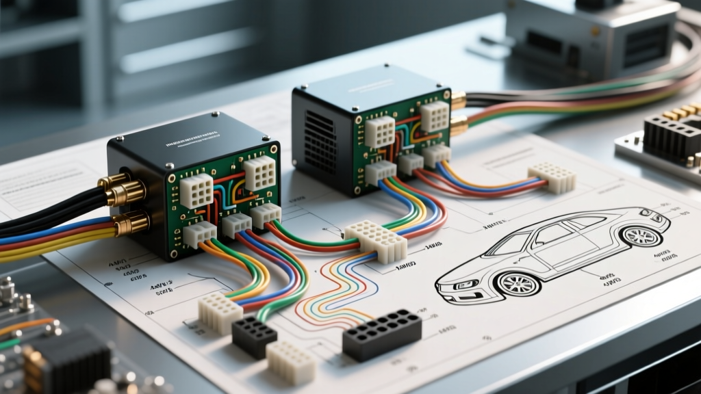
Introduction to Dual Amplifier Configurations
Upgrading from a single monoblock to a multi-amplifier system is a milestone in car audio fabrication. A typical dual-amp setup pairs a high-current Class D monoblock for subwoofers with a Class AB or full-range Class D amplifier for component speakers. However, referencing a generic dual amp wiring diagram is rarely sufficient for high-output systems. The electrical demands of running two separate amplifiers require meticulous planning regarding current draw, voltage drop, and signal routing. According to the Mobile Electronics Association, improper power distribution and grounding are responsible for over 70% of premature amplifier failures and alternator whine issues in multi-amp installations.
This product comparison and selection guide breaks down the three primary dual amp wiring diagram topologies, helping you select the right power distribution kits, wire gauges, and fusing strategies for your specific vehicle and acoustic goals.
Comparing Dual Amp Wiring Diagram Topologies
When designing your power delivery network, you must choose a topology that matches the total amperage draw of your amplifiers. Below, we compare the three standard wiring configurations.
Topology A: The Fused Distribution Block (The Standard Route)
This is the most common and practical dual amp wiring diagram for systems drawing between 120A and 250A total. A single main power wire (typically 1/0 AWG or 4 AWG OFC) runs from the battery to a primary fuse holder within 18 inches of the positive terminal. The wire then feeds into a high-current distribution block mounted in the cabin or trunk. From the block, two separate shorter wires route to each amplifier.
- Best For: Systems with one subwoofer amp (e.g., 1000W RMS) and one full-range amp (e.g., 100W x 4 RMS).
- Kit Selection: Look for solid brass or nickel-plated OFC distribution blocks with set-screw terminals. Avoid blocks with stamped metal contacts, which can loosen under thermal expansion and cause arcing.
Topology B: Daisy-Chaining Amplifiers (The Budget Route)
In this configuration, the main power wire connects to Amplifier 1, and a secondary jumper wire connects the power output terminal of Amplifier 1 to the power input of Amplifier 2. While this saves money on distribution blocks and wire, it is highly discouraged for high-current setups.
- The Danger: The power terminals on most amplifiers are rated for the amperage of that specific amp, not the combined draw of the entire system. Pushing 150A through the set-screws of a 500W amp will cause severe voltage drop, terminal melting, and potential fire hazards.
- When to Use: Only acceptable if both amplifiers are low-draw (e.g., two 4-channel amps drawing less than 40A each combined) and the manufacturer explicitly supports daisy-chaining in their schematic.
Topology C: Independent Dual Runs (The Audiophile Route)
For competition-level SPL builds or massive audiophile systems exceeding 300A, the optimal dual amp wiring diagram involves independent runs. Two separate main power wires route directly from the battery (or a high-capacity alternator/busbar) to each amplifier, each with its own dedicated main fuse.
- Best For: Multi-subwoofer arrays, hair-trick SPL vehicles, and systems utilizing high-output alternators (e.g., Mechman 320A).
- Kit Selection: Requires dual battery feed-through grommets and dual ANL fuse holders at the battery. This completely eliminates cross-talk voltage drop between the subwoofer amp and the mid/high amp during heavy bass transients.
Power Wire & Fuse Selection Chart (AWG & Amperage)
Selecting the correct American Wire Gauge (AWG) is critical. The SAE J1128 standard dictates that low-tension primary cables must handle specific thermal loads, but car audio requires adhering to strict voltage drop limits (ideally under 0.5V drop at max draw). Always select Oxygen-Free Copper (OFC) over Copper-Clad Aluminum (CCA), as CCA requires stepping up one gauge size to match OFC conductivity.
| Total System Draw | Main Feed Wire (OFC) | Branch Wire (OFC) | Main Fuse Type | Branch Fuse Type |
|---|---|---|---|---|
| Under 100A | 4 AWG | 8 AWG | 100A ANL | 40A-60A AGU/MIDI |
| 100A - 150A | 2 AWG or 1/0 AWG | 4 AWG | 150A ANL | 60A-80A MIDI |
| 150A - 250A | 1/0 AWG | 4 AWG | 250A ANL / Class T | 80A-120A MIDI |
| Over 250A | 00 AWG (2/0) | 2 AWG or 1/0 AWG | Class T / ANL Limit | 150A+ ANL |
Note: ANL fuses are preferred over AGU fuses for main power due to their higher interrupting capacity and resistance to shattering under high-voltage short circuits.
Remote Turn-On (REM) Wiring Strategies
A standard dual amp wiring diagram shows a simple split of the head unit's blue/white remote turn-on wire. However, most aftermarket head units limit their REM output to 200mA - 300mA. Two modern amplifiers, especially those with internal cooling fans or digital signal processors (DSPs), can easily draw 400mA+ combined, leading to voltage sag and the amplifiers failing to turn on.
The Bosch Relay Solution
To protect your head unit and ensure a solid 12V+ trigger signal, integrate a standard 30A Bosch-style automotive relay into your REM circuit:
- Pin 86: Connect to the head unit's REM wire (Blue/White).
- Pin 85: Connect to a clean chassis ground.
- Pin 30: Connect to a fused 12V+ constant or switched accessory source.
- Pin 87: Connect to the REM terminals of both amplifiers (use a small 18 AWG distribution block or Y-splitter).
This setup ensures your amplifiers receive a robust, high-current 12V signal without straining the delicate internal switching transistor of your stereo.
Grounding & RCA Signal Routing Best Practices
According to installation guidelines published by Crutchfield, proper grounding and signal isolation are what separate a professional installation from an amateur one.
Establishing a Star Ground
When wiring dual amplifiers, avoid daisy-chaining the ground wires from one amp to another. Instead, use a 'star ground' topology. Run individual 4 AWG ground wires from each amplifier to a single, centralized grounding point on the vehicle's chassis. Use a brass wire brush to remove all paint, primer, and rust down to bare steel. Secure the 5/16-inch ring terminals using a stainless steel bolt and a flange nut, torqued to approximately 50 in-lbs. Coat the terminal in dielectric grease to prevent galvanic corrosion.
RCA Routing to Prevent Alternator Whine
Alternator whine is caused by electromagnetic interference (EMI) inducing a voltage into the RCA shield. To prevent this in a dual-amp setup:
- Route all RCA cables and speaker wires down the opposite side of the vehicle's cabin from the main power wires.
- Use high-quality, twisted-pair, shielded RCA cables.
- If crossing power and signal wires is unavoidable, do so at a strict 90-degree angle to minimize the surface area for EMI induction.
Expert Troubleshooting Matrix
Even with a perfect dual amp wiring diagram, real-world variables can cause issues. Use this diagnostic matrix to troubleshoot common multi-amp failures.
| Symptom | Probable Cause | Expert Fix |
|---|---|---|
| Amp 1 plays, but Amp 2 shuts off during heavy bass hits. | Voltage drop at the distribution block or undersized main feed wire. | Measure voltage at Amp 2's terminals during bass hits. If it drops below 10.5V, upgrade the main feed to 1/0 AWG OFC and clean the distribution block terminals. |
| High-pitch whine that rises with engine RPM. | Ground loop between the head unit and amplifiers, or a failing alternator diode. | Ensure all amplifiers share the same ground potential. Test with the engine off. If whine disappears, install a ground loop isolator on the RCA lines or check alternator AC ripple. |
| Head unit display dims or resets when amps turn on. | REM wire back-feeding or excessive current draw on the head unit's remote circuit. | Install a 30A Bosch relay to isolate the head unit's REM output from the amplifiers' trigger circuits. |
| Amplifier power terminals melting or smelling of ozone. | Stranded wire fraying, loose set-screws, or CCA wire oxidation. | Trim wires cleanly, use ferrule crimps or solder the tips before inserting into set-screw terminals, and re-torque to 50 in-lbs. |
Final Selection Advice
When selecting your wiring kit for a dual amp wiring diagram, never compromise on copper purity or fuse quality. A premium 1/0 AWG OFC kit with ANL fusing and a solid brass distribution block will outlast the amplifiers themselves, providing a stable, noise-free electrical foundation for your car audio system.