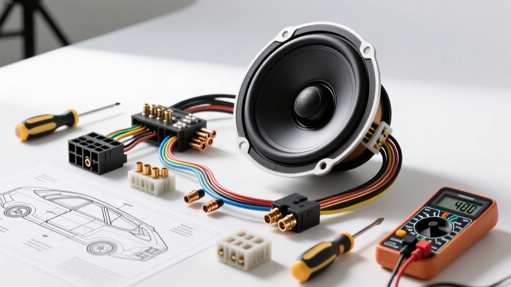
The Blueprint and the Budget: Executing a Single 4-Ohm Load
When integrating aftermarket car audio, the single 4 ohm speaker wiring diagram represents the most fundamental and reliable topology in mobile electronics. Whether you are driving a 10-inch subwoofer via a Class-D monoblock amplifier or powering a 6.5-inch mid-bass driver from a head unit's internal IC, the electrical path remains identical: Amplifier Speaker Positive (SP+) routes to Speaker Terminal 1 (Positive), and Amplifier Speaker Negative (SP-) routes to Speaker Terminal 2 (Negative).
However, a diagram is merely a theoretical map. In the harsh automotive environment—where cabin temperatures can exceed 140°F (60°C) and vibrations constantly stress mechanical joints—executing this diagram requires precise tooling, high-grade materials, and a strict budget. Jumping into an install without a comprehensive Bill of Materials (BOM) and tool analysis inevitably leads to voltage drops, thermal runaway at the terminals, and amplifier protection faults. This guide breaks down the exact cost and tool requirements to execute a flawless single 4-ohm speaker wiring diagram.
Deconstructing the Single 4 Ohm Speaker Wiring Diagram
Before purchasing materials, we must define the electrical parameters of the circuit. A nominal 4-ohm speaker presents a 4-ohm AC impedance load to the amplifier. This is the sweet spot for mobile audio: it allows stereo amplifiers to deliver their rated RMS wattage safely without triggering thermal protection, and it keeps mono subwoofer amplifiers operating efficiently without drawing excessive current from the vehicle's charging system.
Amplifier Terminal Pinout & Wire Routing
Most modern amplifiers utilize either set-screw terminal blocks or Euro-style Phoenix connectors for speaker outputs. The pinout for a single 4-ohm load is straightforward:
- Pin 1 (SP+ / Positive): Connects to the speaker's positive terminal (typically marked with a red dot or '+' symbol). Use standard automotive wire color coding: solid color (e.g., Blue or White) for positive.
- Pin 2 (SP- / Negative): Connects to the speaker's negative terminal (marked with a black dot or '-' symbol). Use a wire with a black stripe (e.g., Blue with Black Stripe) to maintain polarity consistency.
Expert Note: Never rely on the amplifier's internal bridging circuitry if you are only wiring a single speaker to a stereo channel. Always use the designated left or right channel terminals to maintain the 4-ohm load per channel.
Comprehensive Tool Requirements Analysis
The difference between a reliable 10-year installation and a failed system that melts a terminal block lies entirely in the tools used for termination. Cheap, non-ratcheting tools create cold crimps, leading to high resistance and heat generation.
Essential Hand Tools & Diagnostic Gear
- Precision Wire Strippers: Avoid cheap dial-strippers that nick the copper strands, reducing the effective AWG and creating a weak point. Invest in a Knipex 12 62 180 or a Titan 11230 ratcheting wire stripper. These tools cleanly remove insulation without scoring the Oxygen-Free Copper (OFC) strands.
- Ratcheting Crimper: A ratcheting crimper (such as the Preciva AWG 10-24 or Knoweasy ratcheting terminal tool) ensures that the crimp barrel is fully compressed around the wire strands. The ratchet mechanism prevents the tool from releasing until the exact manufacturer-specified compression force is achieved, guaranteeing a gas-tight, cold-weld connection.
- Digital Multimeter (DMM): Essential for verifying DC resistance and checking for shorts before applying power. A Fluke 115 or an Innova 3320 is required to measure the voice coil's DC resistance accurately.
- Heat Gun & Soldering Station: For heat-shrink termination and optional tinning. A Milwaukee M18 cordless heat gun or a Hakko FX-888D soldering station ensures proper adhesion of adhesive-lined marine heat shrink.
Material Cost Breakdown: Wire, Terminals, and Hardware
When analyzing the cost of a single 4 ohm speaker wiring diagram, you must choose between Copper Clad Aluminum (CCA) and Oxygen-Free Copper (OFC). According to SAE J1128 standards for low-tension primary cables, copper purity and strand count dictate current-carrying capacity. CCA wire has 30% less conductivity than OFC, requiring you to step up one full AWG size to achieve the same current flow. For this analysis, we mandate OFC wire for long-term reliability and accurate impedance delivery.
Bill of Materials (BOM) & Cost Estimate
The following table outlines the exact materials and estimated costs for a standard 15-foot run from the amplifier to a single 4-ohm subwoofer or mid-bass driver.
| Component | Specification / Rating | Quantity | Est. Cost (USD) |
|---|---|---|---|
| Speaker Wire (Subwoofer) | 12 AWG OFC, Dual Conductor, Jacketed | 15 ft | $22.00 |
| Speaker Wire (Mid-Bass) | 16 AWG OFC, Dual Conductor, Jacketed | 15 ft | $14.00 |
| Spade Terminals (Speaker) | 12-10 AWG Insulated Male Spade (Sub) / 16-14 AWG (Mid) | 4 Pack | $6.50 |
| Butt Connectors (Amp Side) | 12 AWG Heat Shrink Butt Splices (Adhesive Lined) | 4 Pack | $5.00 |
| Cable Tie Downs & Zip Ties | Adhesive-backed mounts, UV-resistant nylon | 1 Kit | $8.00 |
| Grommet & Loom | 1/2" Split Loom, 3/4" Firewall Grommet (if routing to trunk) | 1 Kit | $7.50 |
| Total Estimated Material Cost (Subwoofer Configuration) | $49.00 | ||
Cost Analysis Note: While big-box auto parts stores sell $10 CCA wire kits, the $49 OFC investment prevents the hidden costs of replacing melted amplifier terminals or diagnosing mysterious clipping issues caused by wire resistance.
Execution: Step-by-Step Wiring & Termination
With the BOM acquired and tools calibrated, execute the single 4 ohm speaker wiring diagram using the following professional termination sequence:
- Strip the Jacket: Remove 3/4" of the outer PVC jacket. Separate the positive and negative conductors.
- Strip the Conductors: Remove 5/16" of insulation from the individual 12 AWG or 16 AWG strands. Twist the strands tightly in a clockwise direction to prevent fraying during crimping.
- Slide on Heat Shrink: Critical Step: Always slide the adhesive-lined heat shrink onto the wire before crimping the terminal. Forgetting this step requires cutting the terminal off and starting over.
- Crimp the Terminal: Insert the twisted wire into the metal barrel of the spade terminal until the strands touch the insulation grip. Use the ratcheting crimper on the correct die setting (usually marked '12-10' or '16-14'). Squeeze until the ratchet releases.
- Apply Heat: Use the heat gun to shrink the insulation sleeve. The adhesive lining should melt and squeeze slightly out of the edges, creating a waterproof, vibration-proof seal against corrosion.
- Amplifier Connection: If using set-screw terminals, tin the bare wire with a soldering iron before inserting it into the amplifier block. This prevents the set-screw from crushing and severing the soft copper strands, which would reduce the connection to a 16 AWG bottleneck.
Expert Troubleshooting & Impedance Verification
Before turning on the head unit or connecting the amplifier's remote turn-on lead, you must verify the circuit. As detailed in Fluke's electrical testing guidelines, measuring DC resistance is the only way to confirm your wiring diagram matches the physical load.
The DMM Verification Test
Set your Digital Multimeter to the lowest Ohms (Ω) setting. Touch the probes together to measure the internal resistance of your test leads (usually 0.2Ω to 0.5Ω). Subtract this from your final reading.
- Expected Reading: A nominal 4-ohm speaker will typically measure between 3.2Ω and 3.8Ω on a DMM. This is because a multimeter measures DC resistance (Re), while the 4-ohm rating is an AC impedance (Z) average across the frequency spectrum.
- Reading 'OL' or Infinite: You have an open circuit. Check the spade terminals at the speaker basket for a loose crimp or a broken strand inside the PVC jacket.
- Reading 0.0Ω to 0.5Ω: You have a dead short. The positive and negative wires are touching somewhere along the routing path, or the voice coil is burnt out.
Symptom-Cause-Fix Decision Tree
If the amplifier enters protection mode immediately upon receiving the 12V Remote signal, use this diagnostic tree:
- Symptom: Amp Protect Light flashes red instantly.
- Cause 1: Spade terminal at the speaker is touching the metal chassis or subwoofer basket.
- Fix: Disconnect, inspect heat shrink, and apply liquid electrical tape to the exposed metal neck of the spade terminal.
- Cause 2: Amplifier output impedance mismatch (e.g., amp is 2-ohm stable, but a short in the wire dropped the load below 1 ohm).
- Fix: Measure resistance at the amplifier terminals. If below 3.0Ω, trace the wire for pinched insulation.
- Cause 1: Spade terminal at the speaker is touching the metal chassis or subwoofer basket.
Conclusion
Successfully executing a single 4 ohm speaker wiring diagram is less about the complexity of the circuit and more about the precision of the execution. By investing roughly $50 in high-purity OFC wire, adhesive-lined terminals, and utilizing a ratcheting crimping strategy, you ensure that the electrical signal reaches the voice coil with zero resistance bottlenecks. For further reading on matching amplifier RMS outputs to specific speaker topologies, consult the extensive wiring archives at Crutchfield's Learning Center. Always measure twice, crimp once, and let the multimeter verify your work before applying power.