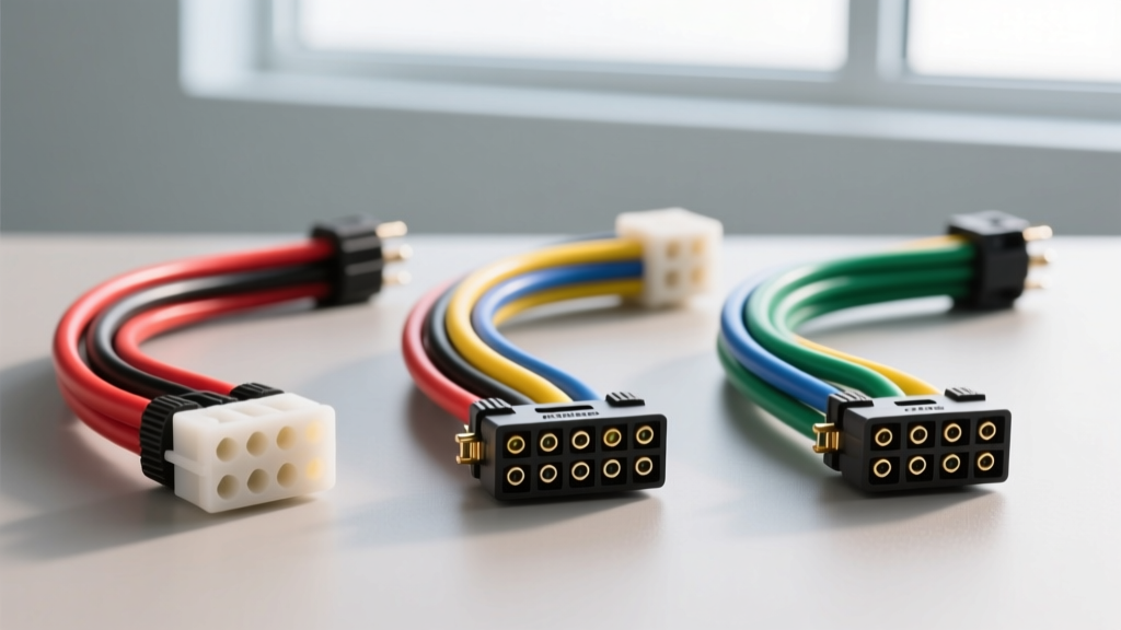
Decoding the Blueprint: Why Speaker Wiring Diagrams Matter
When upgrading a factory audio system, the manufacturer's speaker wiring diagrams are only half the battle. To successfully integrate an aftermarket head unit or amplifier without losing steering wheel controls, chimes, or factory amplification, you must rely on vehicle integration harnesses. However, not all harness documentation is created equal. For professional installers and DIY enthusiasts alike, the clarity, accuracy, and technical depth of the included speaker wiring diagrams dictate the success of the build.
In this product comparison and selection guide, we analyze the wiring diagrams and technical schematics provided by the top three automotive integration brands: Metra Electronics, Axxess Interfaces, and PAC (Peripheral Electronics). Specifically, we will evaluate their documentation for the notoriously complex General Motors Class 2 Data Bus systems (1999-2006 Silverado, Tahoe, Suburban), comparing how each brand guides you through pinouts, impedance matching, and data-bus decoding.
The Contenders: Documentation & Diagram Quality
Before cutting a single wire or crimping a Delphi Packard 150 terminal, an installer must review the harness schematic. A high-quality diagram does more than show wire colors; it illustrates data bus topology, DIP switch configurations, and internal logic board routing.
Metra Electronics: The Standardized Approach
Metra is the industry giant, and their speaker wiring diagrams strictly adhere to the Consumer Technology Association (CTA-2015) color code standards. For non-amplified GM applications (like the Metra 70-2003), their diagrams are exceptionally clean. They utilize standard EIA color coding: Tan/Gray for Left Front, Light Green/Dark Green for Right Front, Brown/Yellow for Left Rear, and Dark Blue/Light Blue for Right Rear.
However, when dealing with amplified Bose systems requiring data-bus integration (e.g., Metra GMOS-01), their diagrams can sometimes feel overly simplified. They excel at showing the 18 AWG stranded copper signal paths and 12 AWG power/ground runs, but advanced installers often find the internal logic of the Class 2 data decoding chip obscured. Metra's diagrams prioritize 'plug-and-play' simplicity over deep electrical troubleshooting, making them ideal for beginners but occasionally frustrating for master technicians diagnosing CAN-bus faults.
Axxess Interfaces: The Amplified System Specialists
Axxess (now part of the Metra family but operating with distinct engineering) shines in complex, amplified environments. The speaker wiring diagrams for the Axxess GMOS-04 are widely considered the gold standard for GM Bose retention. Their schematics explicitly map the 24-pin Delphi connector, detailing not just the speaker outputs, but the critical Class 2 Data pin (Pin B7) and the Amp Turn-On circuit (Pin B10).
What sets Axxess diagrams apart is the inclusion of impedance warning matrices. Factory Bose speakers operate at 2 ohms, while aftermarket replacements are typically 4 ohms. Axxess diagrams include detailed notes on how the internal line-level converters step down the speaker-level signals to RCA pre-outs without triggering the Body Control Module (BCM) to throw a Diagnostic Trouble Code (DTC) for an open circuit. Their documentation frequently includes multimeter testing points, advising installers to verify a 5V-7V square wave on the Class 2 data line before finalizing the connection.
PAC (Peripheral Electronics): The Logic-Board Deep Dive
PAC approaches their speaker wiring diagrams from an electrical engineering perspective. The PAC RPAC-GM11 chime retention module documentation reads like an OEM service manual. Instead of just showing a black box labeled 'Data Module,' PAC diagrams often illustrate the signal flow from the factory BCM, through the optocouplers on the PAC logic board, and out to the aftermarket radio's switched 12V trigger.
For installers building custom subwoofer enclosures and tapping into the factory rear speaker leads, PAC's diagrams are invaluable. They clearly denote the internal low-pass filter crossover points and provide exact pinouts for the Molex MX150 connectors used on the harness pigtails. PAC also provides comprehensive troubleshooting trees within their diagrams, helping technicians isolate ground loop whine caused by improper 10 AWG grounding at the factory chassis bolt.
Wire Color & Pinout Comparison Matrix
When selecting a harness, cross-referencing the brand's speaker wiring diagrams against the vehicle's OEM service manual is critical. Below is a comparison of how each brand documents the critical GM 24-Pin Class 2 connector.
| Feature / Pinout | Metra (GMOS-01) | Axxess (GMOS-04) | PAC (RPAC-GM11) |
|---|---|---|---|
| Class 2 Data (Pin B7) | Standard Purple Wire | Purple w/ Inline Diagnostic LED | Purple w/ Logic Board Schematic |
| Amp Turn-On (Pin B10) | Blue/White (18 AWG) | Blue/White w/ Relay Bypass Note | Blue/White (Fused internally) |
| 12V Battery (Pin B9) | Yellow (12 AWG) | Yellow (12 AWG) + Capacitor Note | Yellow (12 AWG) + Diode Protection |
| Chime Retention Path | Simplified Block Diagram | Detailed Audio Mixing Schematic | Full Optocoupler Logic Flowchart |
| Impedance Matching Notes | Basic 4-ohm Warning | Extensive 2-ohm vs 4-ohm Matrix | Line-Level Output Gain Staging Chart |
Selection Guide: Choosing the Right Diagram for Your Build
Selecting the correct harness—and trusting its accompanying speaker wiring diagrams—depends entirely on your end goal and technical proficiency.
- For Basic Head Unit Swaps (Non-Amplified): Choose Metra. Their diagrams are straightforward, perfectly color-matched to CTA standards, and require minimal electrical theory to execute. You simply match solid colors to positive terminals and striped colors to negative terminals.
- For Factory Amp Bypass & Subwoofer Integration: Choose Axxess. If you are using a Axxess interface to pull a clean, full-range signal from a factory Bose amplifier to feed an aftermarket DSP, their diagrams provide the exact gain-staging and impedance data needed to prevent signal clipping and BCM faults.
- For Custom Fabrication & Advanced Troubleshooting: Choose PAC. If you are building a complex system requiring custom relay setups, chime volume attenuation, or CAN-bus signal sniffing, PAC's engineering-level schematics provide the internal logic required to splice safely without corrupting the vehicle's data network.
Expert Troubleshooting: When the Diagram Fails
Even the best speaker wiring diagrams cannot account for 20 years of chassis corrosion, previous botched installations, or mid-year production splits by General Motors. When the schematic doesn't match the vehicle in your bay, use this decision tree:
- Symptom: No Turn-On / Radio Dead.
- Cause: Class 2 Data Bus failure or missing 12V constant.
- Fix: Ignore the harness diagram's data wire temporarily. Use a digital multimeter (DMM) to probe Pin B9 for 12V constant and Pin B10 for switched 12V. If the BCM is asleep, the data bus will read 0V. Wake the BCM by opening the driver door or turning the key to ACC.
- Symptom: Weak Bass / Hollow Sound.
- Cause: Phase cancellation due to reversed polarity.
- Fix: GM factory wiring often deviates from standard CTA colors in the rear channels. Verify polarity using a 9V battery test or an audio phase tester. According to CTA-2015 standards, the speaker wire with the black stripe or secondary tracer is negative. Never rely solely on the printed diagram if the physical wire lacks the stripe.
- Symptom: Alternator Whine in Speakers.
- Cause: Ground loop induced by sharing a chassis ground with high-current accessories.
- Fix: The SAE J1128 standard dictates strict voltage drop limits for automotive primary cable. Ensure your harness ground (Pin B8) is terminated to bare, unpainted metal using a ring terminal, and verify the ground wire is a minimum of 12 AWG to handle the return current without inducing electromagnetic interference (EMI) into the 18 AWG speaker signal wires.
Final Verdict
Mastering car audio installation requires more than just following colored lines; it demands a deep understanding of the electrical architecture behind the dash. While Metra provides the most accessible speaker wiring diagrams for standard applications, Axxess and PAC offer the technical depth required for modern data-bus integration and complex impedance matching. Always cross-reference your harness schematic with a factory service manual, verify your AWG ratings, and respect the data bus. Your ears—and your vehicle's BCM—will thank you.