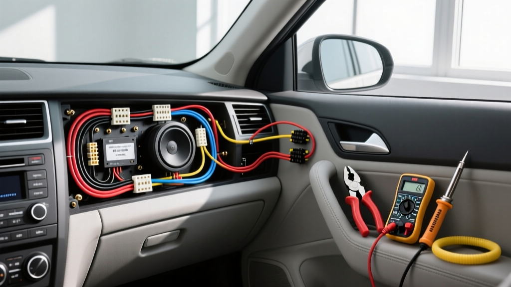
Introduction to 12V Bluetooth Module Integration
Retrofitting a classic vehicle or integrating modern streaming capabilities into a factory head unit requires a precise approach to automotive electrical systems. When executing a hidden installation, relying on a comprehensive diy bluetooth speaker wiring diagram is the difference between a seamless, noise-free audio experience and a frustrating ground-loop nightmare. This guide breaks down the exact tooling, material costs, and technical specifications required to wire a 12V Bluetooth audio receiver module (such as a CSR8645 or Qualcomm aptX HD board) directly into a vehicle's 12V accessory circuit and downstream amplifier or factory speaker harness.
The Core DIY Bluetooth Speaker Wiring Diagram
Most aftermarket automotive Bluetooth receiver modules utilize a standardized 5-pin or 6-pin Molex or JST connector for power and audio routing. Below is the standard pinout configuration for a 12V automotive Bluetooth integration module. Always verify with your specific manufacturer's datasheet, as pinouts can vary between OEM-style harnesses and bare PCB modules.
| Pin Number | Function | Standard Wire Color | AWG Rating | Connection Point |
|---|---|---|---|---|
| 1 | +12V Constant (B+) | Yellow | 18 AWG | Fuse Box (Always Hot) via 2A Inline Fuse |
| 2 | +12V Accessory (ACC) | Red | 18 AWG | Ignition Switch or Radio ACC Circuit |
| 3 | Chassis Ground (GND) | Black | 16 AWG | Bare Metal Chassis Point (Star Ground) |
| 4 | Left Audio Out (+) | White | 20 AWG Shielded | Head Unit / Amp RCA or High-Level Input |
| 5 | Right Audio Out (+) | Gray | 20 AWG Shielded | Head Unit / Amp RCA or High-Level Input |
| 6 | Audio Ground (-) | White/Gray Stripe | 20 AWG Shielded | Isolated Audio Ground (if required) |
Comprehensive Tool Requirements & Cost Breakdown
Executing a professional-grade installation requires moving away from cheap crimp connectors and electrical tape. According to the IPC/WHMA-A-620 standards for cable assemblies, proper crimping and insulation are mandatory for automotive environments subjected to high vibration and thermal cycling. Below is the Bill of Materials (BOM) and tooling cost analysis for a single-vehicle Bluetooth integration.
Capital Tooling Investment
- Precision Wire Strippers: Klein Tools 11055 (10-20 AWG). Essential for avoiding copper strand nicking. Estimated Cost: $28.00
- Ratchet Crimper: Titan 11230 or equivalent for non-insulated open barrel terminals. Ensures consistent crimp pressure. Estimated Cost: $35.00
- Digital Multimeter: Fluke 115 or Innova 3320 for verifying ACC voltage and checking ground continuity. Estimated Cost: $45.00 - $250.00
- Heat Gun: Wagner HT1000 for sealing adhesive-lined heat shrink tubing. Estimated Cost: $25.00
Consumable Materials & Hardware
| Material | Specification | Purpose | Estimated Cost |
|---|---|---|---|
| Automotive Primary Wire | 16-18 AWG GXL (Cross-linked) | Power and Ground routing | $12.00 / 25ft |
| Shielded Audio Cable | 20 AWG Twisted Pair w/ Drain | Line-level audio signal transmission | $18.00 / 10ft |
| Inline Fuse Holder | AGC Glass or Mini-ATM (2A) | Overcurrent protection for B+ circuit | $4.50 |
| Wire Taps | Posi-Tap (Red/Blue) | Non-destructive ACC signal tapping | $8.00 / 4-pack |
| Terminals | Ring terminals (8-10 stud) | Chassis ground termination | $6.00 / 25-pack |
| Heat Shrink | 3M Dual-Wall Adhesive Lined | Environmental sealing & strain relief | $14.00 |
Total Consumable Cost: ~$62.50 (excluding the Bluetooth module itself, which ranges from $25 for basic boards to $90 for audiophile-grade aptX HD modules).
Wire Gauge & Material Specifications (SAE Standards)
When reviewing any diy bluetooth speaker wiring diagram, the most common point of failure is the use of standard PVC-jacketed wire. Automotive environments demand Cross-Linked Polyethylene (XLPE) insulated wire, specifically GXL or TXL grades. As outlined in the SAE J1128 standard for low-tension automotive cables, GXL wire features a thinner insulation wall than standard primary wire, allowing for tighter routing behind dashboards, while maintaining a high-temperature rating of up to 125°C. This is critical when routing wires near the HVAC heater core or steering column.
For the audio signal lines, standard 18 AWG speaker wire is unacceptable for low-level RCA connections. You must use 20 AWG shielded, twisted-pair cable. The twisting of the positive and negative conductors rejects common-mode electromagnetic interference (EMI) generated by the vehicle's alternator and CAN-bus data lines, while the braided shield provides a dedicated drain path for high-frequency RF noise.
Step-by-Step Installation & Grounding Protocol
The physical execution of the wiring diagram requires strict adherence to grounding protocols to prevent alternator whine—a high-pitched noise that fluctuates with engine RPM.
- Locate the ACC Circuit: Use a multimeter to identify a 12V switched source at the back of the factory head unit or fuse panel. Do not use a cigarette lighter circuit, as these often introduce switching noise from other accessory modules.
- Tap the ACC Wire: Avoid Scotch-Loks, which cut through the copper strands and cause voltage drop over time due to oxidation. Use a Posi-Tap connector to bridge the Red ACC wire to the vehicle's harness.
- Establish a Star Ground: The Black GND wire must be terminated to a bare metal chassis point. Remove any paint, powder coating, or rust using a wire brush or sandpaper. Apply a small amount of dielectric grease over the ring terminal after torquing the M6 or M8 bolt to 8-10 Nm to prevent future corrosion.
- Fuse Placement: The 2A inline fuse on the Yellow B+ constant wire must be placed within 6 inches of the power source tap, not near the module. This ensures the entire length of the wire is protected against short circuits.
- Audio Routing: Route the shielded audio cables on the opposite side of the vehicle's center console from the main power harness and OBD-II data lines to prevent inductive coupling.
Real-World Troubleshooting: Eliminating Alternator Whine
If your completed installation produces a whining noise through the speakers, the issue is almost certainly a ground loop. This occurs when the Bluetooth module and the downstream amplifier are grounded at different chassis points, creating a voltage potential difference that travels through the audio shield wire. According to expert integration guides from Crutchfield's car audio installation resources, resolving this requires a unified ground topology.
The Fix: Ensure the Bluetooth module's audio ground (Pin 6) and chassis ground (Pin 3) are tied to the exact same grounding block as your amplifier. If the module features an isolated audio ground, do not tie it to the chassis; instead, run it directly to the amplifier's RCA ground shield. In severe cases where the vehicle's factory alternator diode is failing, installing a 12V DC power line noise filter (LC filter) on the B+ and ACC lines before the module will attenuate the ripple voltage.
Conclusion
Building a custom Bluetooth audio integration is highly rewarding and cost-effective compared to replacing a classic car's entire dashboard with a modern double-DIN unit. By strictly following the pinout diagram, investing in SAE-rated GXL wire, utilizing proper crimping methodologies, and prioritizing a unified star-ground topology, you will achieve a factory-level, noise-free streaming experience. The upfront cost of quality tooling pays dividends in reliability, ensuring your wiring harness survives the harsh thermal and vibrational realities of the automotive environment.