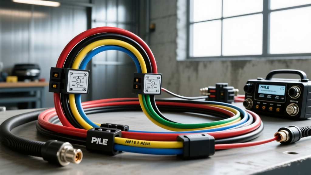
Introduction to Pyle Marine Audio Wiring
Installing a stereo in a marine environment is fundamentally different from a standard automotive installation. Saltwater, humidity, UV exposure, and constant vibration demand strict adherence to marine electrical standards. Pyle marine head units (such as the PLMRKT and PLR series) offer excellent value and durability, but their longevity depends entirely on how well you execute the wiring. This beginner-friendly guide breaks down the standard Pyle marine radio wiring diagram, translates the color codes into actionable steps, and highlights the critical differences between automotive and marine electrical practices.
Understanding the Pyle Marine Radio Wiring Diagram
Pyle utilizes the standard EIA/CEA (Electronic Industries Alliance) color code for its marine and automotive head units. This universal standard ensures that whether you are upgrading an existing system or wiring a new console from scratch, the pinout and wire functions remain consistent. Below is the comprehensive reference chart for your Pyle marine radio harness.
| Wire Color | Function | Recommended AWG | Marine Installation Note |
|---|---|---|---|
| Yellow | B+ (12V Constant / Memory) | 14 or 16 AWG | Connect to an unswitched bus bar with an inline fuse to retain station presets. |
| Red | ACC (12V Switched) | 14 or 16 AWG | Route to a dedicated accessory rocker switch or switched bus bar on the dash. |
| Black | GND (Chassis Ground) | 14 or 16 AWG | Must terminate at a dedicated DC negative bus bar, NEVER to the engine block. |
| Blue | Power Antenna / Amp Remote | 18 AWG | Use to trigger external marine amplifiers or power a motorized antenna. |
| Orange | Illumination / Dimmer | 18 AWG | Connect to the boat's navigation light circuit to dim the display at night. |
| White / White-Black | Front Left Speaker (+ / -) | 16 or 18 AWG | Keep the negative (black-striped) wire isolated. Do not ground to the hull. |
| Gray / Gray-Black | Front Right Speaker (+ / -) | 16 or 18 AWG | Ensure proper phasing; reverse polarity causes severe bass cancellation. |
| Green / Green-Black | Rear Left Speaker (+ / -) | 16 or 18 AWG | Route away from high-current DC cables to prevent alternator whine. |
| Purple / Purple-Black | Rear Right Speaker (+ / -) | 16 or 18 AWG | Use tinned copper wire only to prevent internal corrosion. |
Marine vs. Automotive: Critical Wiring Differences
The most common mistake beginners make when installing a Pyle marine radio is treating the boat like a car. Marine environments require specialized materials and routing techniques to prevent catastrophic electrical failures.
Tinned Copper vs. Bare Copper
Automotive wire is typically bare copper. In a marine environment, moisture wicks into the insulation via capillary action, causing bare copper to oxidize, turn black, and eventually fail. You must use UL 1426 / SAE J1128 compliant tinned marine wire. The silver-colored tin coating prevents oxidation and ensures a reliable connection for years. According to the BoatUS Marine Wiring Guide, using non-tinned wire in a damp bilge or console environment is a primary cause of marine electrical fires and stereo failures.
Grounding and the DC Negative Bus Bar
In a car, you can ground the black wire to any bare metal on the chassis. Boats are largely constructed of fiberglass, wood, or composite materials, meaning there is no universal "chassis ground." Furthermore, grounding to the engine block can introduce severe alternator whine into your audio system and create stray current corrosion. The Pyle black ground wire must be routed to a dedicated, properly sized DC negative bus bar that leads directly back to the battery bank's negative terminal.
Step-by-Step Beginner Installation Workflow
Step 1: Power and Overcurrent Protection
Boats do not have ignition cylinders. Therefore, the Yellow (Constant) and Red (Switched) wires are managed differently than in a car. 1. Run a 14 AWG tinned copper power wire from the positive bus bar to the helm. 2. Install an inline ATC/ATO fuse holder within 7 inches of the positive power source, as mandated by the American Boat & Yacht Council (ABYC) E-11 Standards for overcurrent protection. 3. Connect the Yellow wire to an unswitched circuit (so your radio retains memory). 4. Connect the Red wire to a switched circuit controlled by a dash rocker switch, allowing you to manually cut power when leaving the boat to prevent parasitic battery drain.
Step 2: Waterproofing Connections
Never use standard vinyl crimp connectors, twist-on wire nuts, or electrical tape in a marine environment. You must use adhesive-lined marine heat shrink butt connectors. 1. Strip exactly 5/16" of insulation from both the Pyle harness wire and your marine-grade extension wire. 2. Insert the wires into the metal barrel of the heat shrink connector and crimp firmly using a ratcheting crimp tool. 3. Apply heat using a heat gun (not a lighter) starting from the center of the connector and moving outward. 4. Stop heating when the adhesive sealant squeezes out slightly from the edges, creating a 100% waterproof, airtight seal.
Step 3: Speaker Wire Routing and Phasing
When wiring the speaker outputs, keep the negative wires (the ones with the black stripe) completely isolated. The internal MOSFET amplifier in your Pyle marine radio uses a bridged output design. If you tie the speaker negative wires together or ground them to the boat's negative bus bar, you will instantly short-circuit and destroy the head unit's internal amplifier IC. Run dedicated 16 AWG or 18 AWG tinned speaker wire directly from the radio to each marine speaker pod.
Troubleshooting Common Marine Stereo Issues
Even with a perfect wiring diagram, marine environments can introduce unique variables. Use this decision matrix to diagnose common post-installation issues.
| Symptom | Probable Cause | Diagnostic Fix |
|---|---|---|
| Radio turns on, but loses presets every time the boat is turned off. | Yellow (Constant) and Red (Switched) wires are swapped, or Yellow is on a switched bus. | Verify the Yellow wire has 12V at all times using a multimeter, even when the dash rocker switches are off. |
| Loud, high-pitched whining noise from speakers that changes with engine RPM. | Alternator whine caused by improper grounding or running RCA/Speaker wires parallel to power cables. | Move the Black ground wire to a clean, dedicated negative bus bar. Re-route speaker wires away from the main DC power harness. |
| Radio display works, but no audio from any speakers. | Speaker negative wires are grounded to the hull or tied together, triggering the amp protection circuit. | Disconnect all speaker wires at the radio. Check for continuity between the speaker negative wires and the boat's ground. There should be zero continuity. |
| Weak, thin bass response and hollow sound. | Speaker wires are out of phase (positive and negative swapped on one or more speakers). | Check the gray/white/green/purple striped wires. Ensure the solid color connects to the speaker's positive (+) terminal and the black-striped wire to the negative (-) terminal. |
| Corrosion (green/white powder) appearing on the back of the radio harness. | Use of bare copper automotive wire or non-adhesive electrical tape allowing moisture ingress. | Cut back the corroded wire until clean tinned copper is visible. Re-terminate using adhesive-lined marine heat shrink connectors. |
Final Inspection and Testing
Before sealing the console or mounting the Pyle radio into the dash, perform a "bench test" inside the boat. Connect the power, ground, and at least one speaker. Turn on the main battery switch, flip the accessory rocker switch, and verify that the unit powers on, retains memory after being shut off, and produces clean audio. Once verified, carefully tuck the excess wire harness behind the dash, ensuring no wires are pinched against sharp fiberglass edges or resting near hot engine components. Proper execution of your Pyle marine radio wiring diagram ensures your audio system will survive the harsh marine elements and provide reliable entertainment on the water for years to come.