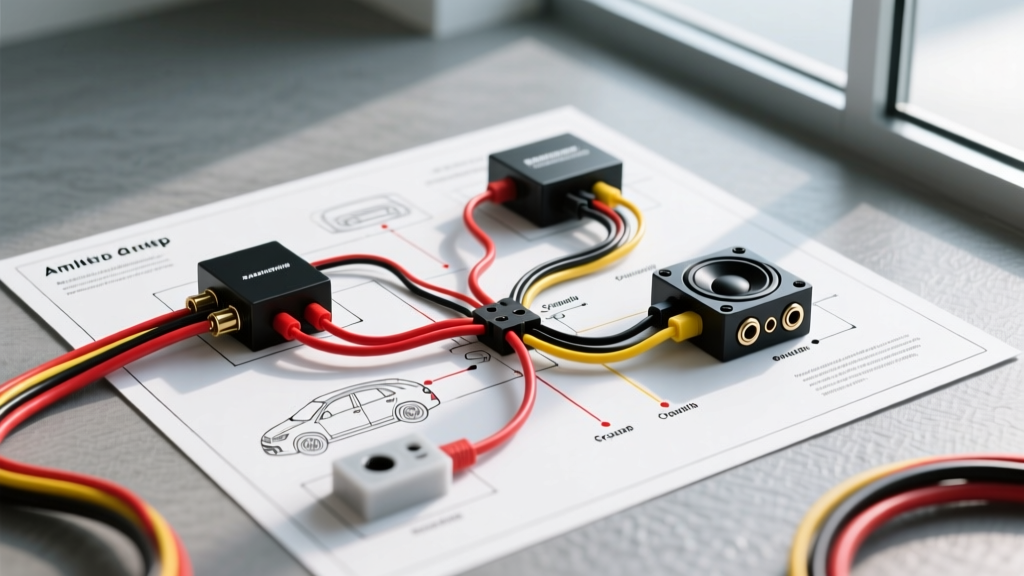
Understanding the Dual-Amplifier Topology
Installing a multi-amplifier system transforms a standard vehicle into a high-fidelity listening environment, but it exponentially increases the complexity of the electrical architecture. When referencing a standard two amp wiring diagram—typically featuring a 4-channel amplifier for component speakers and a monoblock amplifier for subwoofers—the most common point of failure isn't the equipment itself, but the power distribution, grounding topology, and signal routing.
Unlike a single-amp setup, dual-amplifier configurations require precise load balancing at the distribution block, meticulous remote turn-on (REM) current management, and strict adherence to Oxygen-Free Copper (OFC) wiring standards to prevent voltage sag and thermal shutdowns. This step-by-step troubleshooting flow is designed for automotive electrical technicians and advanced DIYers to systematically isolate faults in a dual-amplifier car audio system.
Phase 1: Main Power and Distribution Block Diagnostics
The foundation of any two amp wiring diagram is the main power feed. A dual-amp system drawing a combined 150+ amps requires a robust 1/0 AWG main feed from the battery to a primary distribution block. If one or both amplifiers are entering protect mode or failing to power on, begin with a voltage drop test.
Step 1.1: The Voltage Drop Test
Set your digital multimeter (DMM) to DC Voltage. Place the positive probe on the battery's positive terminal and the negative probe on the amplifier's B+ terminal. With the system playing bass-heavy content at 75% volume, the voltage drop should not exceed 0.2V. A reading higher than 0.5V indicates high resistance, usually caused by undersized wiring, Copper-Clad Aluminum (CCA) wire, or loose set-screw terminals.
- Battery to Firewall: Must be 1/0 AWG OFC wire, protected by an ANL fuse within 18 inches of the battery positive terminal.
- Firewall to Distro Block: 1/0 AWG or 2 AWG depending on cabin routing distance.
- Distro Block to Amplifiers: 4 AWG OFC for runs under 10 feet; 2 AWG for runs exceeding 15 feet.
Step 1.2: Ground Integrity and Torque Specifications
Amplifier ground terminals are a frequent culprit in dual-amp failures. According to SAE J1128 standards for low-tension primary cable, termination resistance must be virtually zero. Sand the chassis grounding point down to bare, shiny metal using 80-grit sandpaper, removing all factory E-coat and primer. Apply a 4 AWG ring terminal crimped with a hex-crimp die, and secure it using a factory chassis bolt or a self-tapping #12 sheet metal screw. The amplifier's set-screw ground terminal should be torqued to exactly 1.5 to 2.0 Nm (15-20 in-lbs). Overtightening will strip the brass terminal block, creating an internal arc.
Phase 2: Remote Turn-On (REM) Circuit Failures
If the main power and ground are verified, but the secondary amplifier (usually the monoblock) fails to power on, the issue lies in the remote turn-on circuit. The blue/white REM wire from an aftermarket head unit is typically limited to a 300mA (0.3A) output. When splitting this signal to feed the REM terminals of two separate amplifiers, the combined current draw can exceed the head unit's limit, causing the voltage to sag below the 6V threshold required to trigger the amplifier's internal relay.
Step 2.1: Diagnosing REM Voltage Sag
Measure the DC voltage at the head unit's blue/white wire with both amplifiers connected. If the voltage drops below 9V, the head unit's internal REM transistor is overloaded. Disconnect the REM wire from the secondary amplifier. If the primary amplifier turns on instantly, you have confirmed a current overload.
Step 2.2: Implementing a Bosch-Style Relay Bypass
To resolve this without damaging the head unit, integrate a standard 12V 30A ISO mini relay into your two amp wiring diagram. Wire the relay as follows:
- Pin 86: Connect to the head unit's blue/white REM wire (Signal trigger).
- Pin 85: Connect to a clean chassis ground.
- Pin 30: Connect to a fused +12V constant or switched source (e.g., from the distribution block).
- Pin 87: Connect to the REM terminals of both amplifiers.
This configuration ensures the head unit only supplies the ~75mA needed to trigger the relay coil, while the relay contacts handle the heavy current required to wake up multiple amplifier power supplies simultaneously.
Phase 3: RCA Signal and Ground Loop Troubleshooting
Alternator whine (a high-pitched noise that rises and falls with engine RPM) is the most common signal issue in dual-amp setups. This occurs when there is a difference in potential between the head unit's ground and the amplifiers' grounds, causing current to flow through the RCA cable shields.
Step 3.1: Isolating the Ground Loop
Do not immediately install a ground loop isolator; this degrades audio quality by rolling off low-end frequencies. Instead, verify the RCA shield continuity. Using your DMM set to resistance (Ohms), measure between the outer metal ring of the RCA plug at the head unit and the outer ring at the amplifier. It should read near 0.0 Ohms. Next, measure the resistance between the head unit chassis and the amplifier chassis. If there is a variance greater than 0.05 Ohms, you have a ground loop.
Step 3.2: Correcting the Shield Grounding
Ensure your RCA cables are routed on the opposite side of the vehicle from the power and speaker wires to prevent electromagnetic interference (EMI). If the RCA cables must cross power wires, they must do so at a strict 90-degree angle. Furthermore, ensure the RCA shields are only grounded at the source (head unit). If you are using a DSP or line output converter (LOC) in the signal chain between the two amps, ensure its ground is tied directly to the main amplifier's ground terminal, not a separate chassis point.
Phase 4: Amplifier Protection Mode & Impedance Checks
If an amplifier powers on but immediately clicks into 'Protect' mode (indicated by a red LED), the internal microprocessor has detected a short circuit, thermal overload, or impedance mismatch. In a two amp wiring diagram, this usually affects the monoblock subwoofer amplifier.
Step 4.1: Speaker Wire Short Detection
Disconnect all speaker wires from the amplifier terminals. Power the amp back on. If the protect light turns off, the amplifier is fine, and the fault is in the speaker wiring or the subwoofer voice coils. Inspect the speaker wire routing. A common failure mode is the set-screw in the amplifier's speaker terminal biting down on the wire jacket rather than the bare copper strands, or a stray strand of copper touching the vehicle chassis.
Step 4.2: Verifying Subwoofer Impedance
Set your DMM to the 200 Ohm range. Measure the resistance at the end of the speaker wires (with the amp disconnected). Remember that DC resistance is roughly 10-15% lower than nominal AC impedance.
- Nominal 4-Ohm DVC Subwoofer (Wired Parallel): Should read ~2.0 Ohms on the DMM.
- Nominal 2-Ohm DVC Subwoofer (Wired Series): Should read ~4.0 Ohms on the DMM.
If your DMM reads 0.5 Ohms or infinite (OL), you have a shorted voice coil or a broken tinsel lead inside the subwoofer, respectively. Consult Crutchfield's amplifier installation guides for specific impedance matching charts based on your exact subwoofer model and amplifier stability rating.
Reference Table: AWG & Distribution Sizing for Two Amp Wiring Diagrams
Use the following specification chart to ensure your power delivery network meets the demands of a dual-amplifier configuration. This data aligns with MECP (Mobile Electronics Certified Professional) best practices for mobile electrical systems.
| System Total RMS Wattage | Main Feed (Battery to Distro) | Main Fuse Rating (ANL) | Distro Output to Amps | Ground Wire Sizing |
|---|---|---|---|---|
| Up to 1000W | 4 AWG OFC | 100A | 8 AWG OFC | Match Power Wire |
| 1000W - 2000W | 2 AWG OFC | 150A | 4 AWG OFC | Match Power Wire |
| 2000W - 3500W | 1/0 AWG OFC | 250A | 4 AWG OFC | Match Power Wire |
| 3500W+ | Double 1/0 AWG or 4/0 AWG | 400A+ | 2 AWG or 1/0 AWG | Match Power Wire |
Final Diagnostic Verification
Once all phases of this troubleshooting flow have been executed, perform a final idle and load test. Start the vehicle and allow the alternator to engage (typically 13.8V to 14.4V). Play a 40Hz sine wave test tone at 0dB. Monitor the voltage at the amplifier B+ terminals. If the voltage remains above 12.0V, the 'Big Three' electrical upgrade (alternator positive, engine block ground, chassis ground) may not be necessary. If voltage drops below 11.5V and the headlights dim severely, the vehicle's charging system cannot support the two amp wiring diagram load, and an alternator upgrade or auxiliary AGM battery must be integrated into the system.