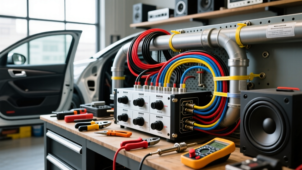
Project Scoping: The True Cost of a 4-Channel Amplifier Installation
Executing a flawless 4 channel amp wiring diagram requires more than just connecting wires to terminals; it demands a strategic approach to material selection, specialized tooling, and an understanding of hidden automotive electrical costs. Whether you are driving a daily commuter or building a competition-level SQ (Sound Quality) vehicle, underestimating the Bill of Materials (BOM) or using inadequate tools will result in voltage drop, thermal throttling, and high-frequency noise interference.
As an automotive electrical specialist, I have broken down the exact tool requirements, material costs, and technical specifications needed to properly wire a 4-channel amplifier. This analysis assumes a standard 75W x 4 RMS Class AB or Class D amplifier drawing approximately 40-50 amps at peak load, requiring a robust 4 AWG power delivery system.
Essential Tool Requirements for a Professional-Grade Install
Consumer-grade wire strippers and electrical tape will not suffice for high-current automotive environments. To meet SAE J1128 standards for battery cable termination and ensure zero-resistance connections, the following specialized tools are mandatory:
- Ratcheting Hex-Crimper (4 AWG to 8 AWG): Indent crimpers leave air pockets that invite corrosion. A hexagonal ratcheting crimper (e.g., Knoweasy or Titan) applies 360-degree radial pressure, cold-welding the copper strands to the terminal.
- Digital Multimeter (True RMS): Required for verifying 12.4V-14.4V DC at the B+ terminal under load, and for checking AC voltage ripple from the alternator. A Fluke 115 or equivalent is recommended for its low-impedance (LoZ) mode, which prevents ghost voltage readings on RCA shields.
- Torque Screwdriver (Nm rated): Amplifier set-screws are easily stripped. Terminals should be torqued to exactly 3.5 to 5.0 Nm depending on the manufacturer spec. Over-tightening severs outer copper strands, creating localized hotspots.
- Wire Brush & Dielectric Grease: For chassis ground preparation. Removing factory e-coat paint down to bare steel is non-negotiable.
- Panel Pry Tools & Trim Removal Kits: Nylon-bladed tools to prevent marring interior plastics and breaking brittle OEM retaining clips during head unit and door panel removal.
Material Cost Breakdown: Wire, Terminals, and Fuses
The market is flooded with Copper-Clad Aluminum (CCA) wire masquerading as Oxygen-Free Copper (OFC). CCA wire has 40% higher resistance than OFC, leading to severe voltage drop over long runs. Always verify the copper purity. Below is the realistic BOM cost for a premium OFC installation.
| Component | Specification | Est. Cost (USD) | Technical Notes & Application |
|---|---|---|---|
| Power Wire | 4 AWG OFC, 17ft | $55.00 | Must handle 60A continuous. See Knukonceptz Kolossus or similar pure copper kits. |
| Ground Wire | 4 AWG OFC, 3ft | $12.00 | Keep ground runs under 18 inches to minimize impedance. |
| Inline Fuse & Holder | ANL 60A or 80A | $18.00 | Must be installed within 12 inches of the positive battery terminal. |
| Speaker Wire | 16 AWG OFC, 50ft | $25.00 | Sufficient for 4 doors. Avoid 18 AWG for runs over 10 feet to prevent high-frequency damping. |
| RCA Interconnects | 2-Channel Twisted Pair (x2) | $40.00 | Must feature a braided shield and high rejection ratio to prevent alternator whine. |
| Terminals | 4 AWG Ring Spades (Tinned) | $10.00 | Tinned copper prevents galvanic corrosion at the battery and amp blocks. |
| Remote Turn-On Wire | 18 AWG Primary Wire | $8.00 | Blue/White stripe standard. Connects to head unit Pin 7 (EIA standard). |
| Distribution Block | 1-in / 2-out (if adding sub amp) | $22.00 | Set-screw type with protective acrylic cover. |
Total Estimated Material Cost: $190.00 (Excluding sound deadening and fabrication materials).
Decoding the 4 Channel Amp Wiring Diagram
A standard 4-channel amplifier terminal block and signal flow diagram requires precise routing to maintain signal-to-noise ratio (SNR). Below is the technical execution of the primary circuit nodes.
1. Power and Ground Pin Configurations
The B+ (Battery Positive) terminal requires the 4 AWG main power wire. This wire must pass through the vehicle's firewall using an existing rubber grommet or a newly drilled hole protected by a rubber firewall bushing. Never route power wires near factory ECU harnesses to avoid inductive interference.
The GND (Chassis Ground) is the most critical point of failure in any car audio system. Locate a factory seatbelt bolt or a dedicated chassis stud. Remove all paint, primer, and rust using a wire wheel attached to a rotary tool. Apply a small amount of petroleum jelly or dielectric grease over the crimped ring terminal after torquing it down to 10 Nm to seal out moisture and prevent oxidation.
2. Signal Routing: RCA vs. High-Level Inputs
If your aftermarket head unit features preamp outputs, route two pairs of RCA cables (Front and Rear) down the opposite side of the vehicle from the power wire. If you are integrating with a factory OEM radio, you will need a Line Output Converter (LOC). Active LOCs (like the AudioControl LC2i) require a 12V+ and Ground reference to power their internal summing circuitry, which adds roughly $15 to your BOM and requires tapping into the accessory fuse panel using an Add-A-Circuit (fuse tap).
3. Remote Turn-On (REM) Circuit
The REM terminal triggers the amplifier's internal power supply relays. Connect an 18 AWG wire to the head unit's "System Remote Control" wire (Standard EIA color: Blue with White stripe). If the head unit lacks this wire, tap into the ignition-switched 12V+ circuit (often the yellow/red wire on OEM harnesses) using a T-tap or, preferably, a soldered and heat-shrunk connection.
Hidden Costs and Real-World Troubleshooting
When analyzing the cost of a 4 channel amp wiring diagram installation, novice installers often forget the secondary costs associated with resolving electrical anomalies post-installation. Consult comprehensive resources like the Crutchfield Amplifier Installation Guide for foundational troubleshooting, but be prepared for these specific real-world scenarios:
Symptom: High-Pitched Alternator Whine that Revs with RPM
- Cause: Ground loop or insufficient alternator ripple filtering.
- Fix: First, verify the amp ground and head unit ground share the same chassis potential using a multimeter (should read 0.00V - 0.05V AC). If the whine persists, the factory charging system is failing. You may need to perform a "Big Three" wiring upgrade (Alternator to Battery+, Battery- to Chassis, Engine Block to Chassis) using 1/0 AWG wire, adding roughly $75 to your project cost.
Symptom: Amplifier Clipping or Thermal Protection at High Volume
- Cause: Voltage drop at the B+ terminal due to undersized wire or CCA wire degradation.
- Fix: Measure DC voltage at the amp's B+ terminal while playing a 50Hz bass test tone at 75% volume. If voltage drops below 11.5V, your 4 AWG wire is insufficient, or your battery's internal resistance is too high. Upgrading to a high-output AGM battery or adding a 1.5 Farad carbon-based capacitor (approx. $80) will stabilize the voltage rail.
Expert Wiring Specifications & Best Practices
To ensure longevity and safety, adhere to these final installation parameters:
- Twist RCA and Speaker Wires: Twisting signal wires tightly (at least 4 twists per foot) creates a common-mode rejection effect, drastically reducing electromagnetic interference (EMI) from the vehicle's ignition system.
- Solder vs. Crimp: While soldering is excellent for 18 AWG signal wires, never solder 4 AWG power wire. Solder can wick under the insulation and create a rigid point that snaps under chassis vibration. Use a high-quality hex crimp and seal it with adhesive-lined marine-grade heat shrink.
- Speaker Wire Polarity: Standard EIA color coding must be strictly followed to maintain acoustic phase. Right Front (Gray/Gray-Black), Left Front (White/White-Black), Right Rear (Purple/Purple-Black), Left Rear (Green/Green-Black). A reversed polarity on a single door speaker will result in destructive acoustic interference, completely destroying the center image of your soundstage.
By accurately forecasting these tool requirements, material costs, and technical specifications, you transform a standard 4-channel amplifier installation from a risky DIY experiment into a reliable, high-fidelity automotive audio system.