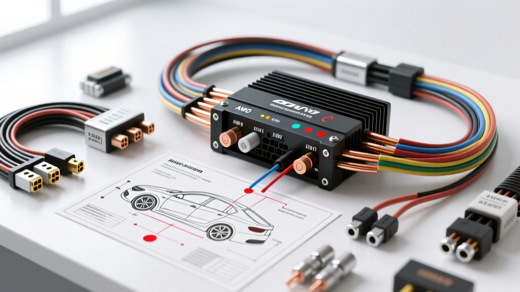
The Physics of High-Current Car Amplifier Wiring
When executing advanced car amplifier wiring for mobile audio systems exceeding 1,000 watts RMS, standard retail installation kits are fundamentally inadequate. High-current environments demand a rigorous understanding of electrical physics, conductor metallurgy, and chassis impedance. This technical deep dive explores the engineering principles required to build a stable, low-noise, and high-efficiency power delivery network for competitive SPL (Sound Pressure Level) or SQ (Sound Quality) vehicles.
Conductor Metallurgy: OFC vs. CCA and SAE Standards
The foundation of reliable car amplifier wiring lies in the conductor material. The market is flooded with Copper-Clad Aluminum (CCA) wire, which is lighter and cheaper but possesses significantly higher electrical resistance than Oxygen-Free Copper (OFC). According to SAE J1128 standards for low-tension primary cables, wire gauge ratings are predicated on pure copper conductivity. Using CCA wire requires upsizing by at least one to two AWG steps to achieve the same ampacity and voltage drop characteristics. Furthermore, CCA is highly susceptible to galvanic corrosion when exposed to oxygen at termination points, leading to catastrophic resistance increases over time.
| AWG Size | OFC Resistance (Ω/1000ft) | CCA Resistance (Ω/1000ft) | Max Ampacity (OFC - SAE) | Max Ampacity (CCA) |
|---|---|---|---|---|
| 4 AWG | 0.2485 | 0.3950 | 125A | 85A |
| 2 AWG | 0.1563 | 0.2480 | 175A | 120A |
| 1/0 AWG | 0.0983 | 0.1560 | 245A | 170A |
Calculating Voltage Drop in Complex Routing
Amplifier power supply capacitors require a stable 13.8V to 14.4V DC rail to operate at rated efficiency. Voltage drop occurs when the resistance of the power and ground cables causes a loss of potential before it reaches the amp's B+ terminal. The formula for DC voltage drop is:
Vd = (2 × L × I × ρ) / A
Where L is the one-way length in meters, I is the current draw in Amperes, ρ is the resistivity of the conductor (1.68 × 10⁻⁸ Ω·m for copper), and A is the cross-sectional area in square meters. For a practical example referenced in the Crutchfield installation guidelines, a Class D monoblock drawing 120A with an 18-foot total round-trip cable run using 4 AWG OFC wire will experience approximately 0.72V of drop. While acceptable, moving to a 150A draw pushes the drop over 1.0V, triggering the amplifier's undervoltage protection circuit. Upsizing to 2 AWG or 1/0 AWG is mandatory for high-draw monoblocks to maintain transient headroom.
Advanced Grounding Topologies & Chassis Preparation
The vehicle chassis serves as the return path to the battery's negative terminal. A common failure mode in car amplifier wiring is treating the chassis ground as a simple mechanical attachment rather than a critical electrical junction. Modern vehicles use high-strength, low-alloy (HSLA) steels and extensive e-coat (electro-deposition) paint processes that act as dielectric insulators.
Chassis Prep and Torque Specifications
To achieve a ground impedance of less than 5 milliohms (mΩ), the grounding surface must be stripped to bare, shiny metal. Use 80-grit sandpaper or a rotary wire brush to remove paint and primer. Once the bare metal is exposed, immediately apply a conductive anti-oxidant compound (such as No-Ox-Id A-Special) to prevent galvanic corrosion and rust formation, which rapidly increases resistance over time.
When securing the ground ring terminal, use a Grade 8 or Class 10.9 metric bolt. For an M8 bolt, the target torque specification is 18–22 Nm (13–16 lb-ft). For an M10 bolt, torque to 35–40 Nm. Never use self-tapping sheet metal screws for high-current grounds; the thread engagement area is insufficient to handle the thermal expansion and current density of a 100A+ return path.
The "Big Three" Upgrade Integration
For systems drawing over 150A, the factory chassis grounding straps are often undersized (typically 8 AWG or 6 AWG). The "Big Three" upgrade involves replacing or supplementing three critical ground/power paths with 1/0 AWG OFC welding cable:
- Alternator B+ to Battery B+: Reduces voltage drop between the charging source and the storage bank.
- Engine Block to Chassis: Ensures the alternator casing (which acts as the negative return for the stator) has a zero-impedance path to the unibody.
- Chassis to Battery Negative: Completes the high-current circuit back to the main storage bank.
Multi-Amplifier Distribution and Fusing Coordination
Systems utilizing multiple amplifiers (e.g., a 4-channel for active front stage and a monoblock for subwoofers) require centralized power distribution. Daisy-chaining power or ground wires from one amplifier to another introduces ground loops and unequal voltage distribution. Instead, use a solid brass or copper distribution busbar mounted to a non-conductive surface.
Overcurrent protection must be coordinated to protect the cable, not just the equipment. The main fuse at the battery must have an Ampere Interrupting Capacity (AIC) sufficient to handle the maximum short-circuit current of the vehicle's alternator and battery combined. AudioControl's technical resources emphasize placing the main fuse within 18 inches of the battery positive terminal to protect the entire length of the power wire.
| Fuse Type | AIC Rating (at 14V) | Best Application | Trip Speed |
|---|---|---|---|
| ANL | 2,700A | Main battery power (up to 300A) | Slow-Blow (Tolerates inrush current) |
| Maxi | 1,000A | Secondary distribution / Mid-current | Medium-Blow |
| Class-T | 20,000A | High-current SPL builds / Lithium banks | Fast-Blow (High interrupting capacity) |
| Circuit Breaker | 3,000A | Marine / High-vibration environments | Variable (Thermal/Magnetic) |
Signal Path Integrity: RCA Routing and EMI Mitigation
High-current power cables generate significant electromagnetic interference (EMI). Alternator whine (a high-pitched noise that scales with engine RPM) is the most common symptom of poor signal routing in car amplifier wiring. The vehicle's alternator outputs a pulsed DC current with AC ripple, creating a fluctuating magnetic field around the power wire.
To mitigate this, RCA signal cables must utilize twisted-pair internal geometry and high-coverage braided shielding to promote common-mode rejection. Route signal wiring down the opposite side of the vehicle's center console from the power cables. If the power and signal cables must intersect, they must cross at exactly 90 degrees to minimize the surface area of magnetic coupling. Never zip-tie RCA cables to the main power harness or factory wiring looms containing CAN-bus or high-current injector circuits.
Diagnostic Troubleshooting: Thermal Shutdown and Voltage Sag
Even with meticulous planning, advanced systems require debugging. If an amplifier enters thermal protection mode despite adequate ventilation, measure the DC resistance of the speaker load at the amplifier's output terminals using a digital multimeter (DMM). Voice coil resistance increases as temperature rises; a subwoofer rated at 2.0 ohms cold may present a 3.5-ohm load when hot, altering the amplifier's damping factor and efficiency curve, causing the output stage to overwork and overheat.
If the amplifier clips prematurely or the headlights dim severely on bass transients, perform a dynamic voltage drop test. Connect the DMM directly to the amplifier's B+ and Ground set-screws (not the battery). Play a 40Hz test tone at 1/2 rated power. If the voltage at the amp terminals drops below 11.5V, the bottleneck is in the wiring or the vehicle's charging system. This indicates the need to verify all crimp connections using a thermal imaging camera; any termination point glowing hotter than ambient temperature by more than 10°C indicates a high-resistance micro-fault requiring re-crimping with a closed-barrel hex die.