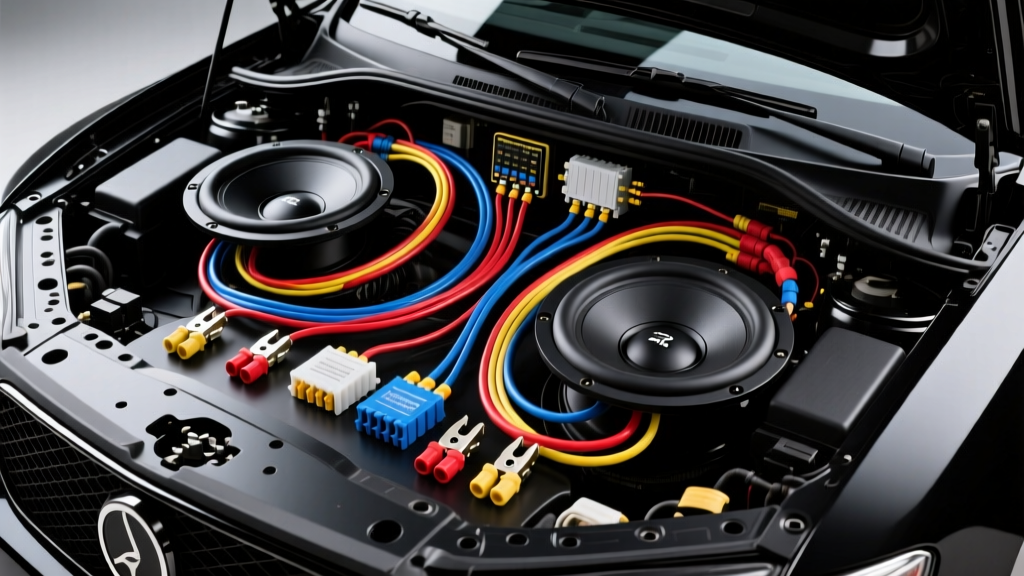
Understanding the Dual 2 Ohm Subwoofer Wiring Diagram Topology
When planning a high-output bass system, referencing an accurate dual 2 ohm subwoofer wiring diagram is only the first step. A Dual Voice Coil (DVC) 2-ohm subwoofer features two separate 2-ohm voice coils, giving the installer two distinct impedance configurations: a 1-ohm parallel load or a 4-ohm series load. While the diagram dictates the electrical path, executing it safely requires a rigorous approach to tooling, material selection, and budget allocation. Cheap wiring kits and improper crimping are the leading causes of thermal runaway, voltage drop, and blown amplifier output stages.
Before purchasing materials, you must decide on your final impedance. A 1-ohm parallel configuration extracts maximum wattage from Class D monoblock amplifiers but demands massive current delivery, requiring premium Oxygen-Free Copper (OFC) wiring and high-amperage ANL fuses. A 4-ohm series configuration halves the current draw, allowing for smaller gauge wire and generating significantly less heat in the amplifier's output transistors, though at the cost of peak wattage.
Decoding the Wiring Configurations
Parallel Wiring (1-Ohm Final Load)
In a parallel setup, both positive terminals and both negative terminals are tied together. This configuration is ideal for amplifiers rated for 1-ohm stability under the CTA-2006 Mobile Audio Amplifier Power Standard.
- Amplifier (+) splits to Subwoofer Coil A (+) and Subwoofer Coil B (+).
- Amplifier (-) splits to Subwoofer Coil A (-) and Subwoofer Coil B (-).
Series Wiring (4-Ohm Final Load)
Series wiring daisy-chains the coils, doubling the impedance. This is the safest route for amplifiers that are only rated down to 2 ohms.
- Amplifier (+) connects to Subwoofer Coil A (+).
- A jumper wire connects Subwoofer Coil A (-) to Subwoofer Coil B (+).
- Subwoofer Coil B (-) connects back to Amplifier (-).
Mandatory Tooling for High-Current Subwoofer Loads
Automotive environments subject wiring to extreme vibration, temperature fluctuations, and moisture. Hand-crimping 4 AWG wire with standard pliers violates IPC/WHMA-A-620 crimping standards and creates high-resistance micro-gaps that will melt under 100+ amp loads. The following tools are non-negotiable for a reliable installation:
- Ratcheting Crimper (4 AWG to 8 AWG): Tools like the Knipex 97 52 50 or Titan 19500 ensure a uniform, gas-tight crimp. The ratcheting mechanism prevents the release of the tool until the exact compression depth is reached, eliminating loose strands.
- Digital Multimeter (DMM): A Fluke 115 or equivalent True-RMS meter is required to verify the exact ohm load at the amplifier terminals before applying 12V power. A reading of 0.8 ohms instead of 1.0 ohms indicates a short or a damaged voice coil.
- Heat Gun with Reflector Nozzle: Required for activating dual-wall adhesive heat shrink. A standard lighter will scorch the insulation and fail to melt the internal polyamide adhesive.
- Wire Stripping Jig: Prevents nicking the outer strands of OFC wire, which reduces the overall current-carrying capacity and creates a weak point for wire fatigue.
Comprehensive Cost Analysis: Budget CCA vs. Pro-Grade OFC
The market is flooded with inexpensive Copper-Clad Aluminum (CCA) wiring kits. While CCA saves money upfront, it has 40% higher electrical resistance than OFC and is highly susceptible to galvanic corrosion and snapping under subwoofer-induced vibration. Below is a cost breakdown comparing a generic big-box store kit to a professional-grade OFC setup for a 1200W (1-ohm) system.
| Component | Budget CCA Kit Cost | Pro-Grade OFC Setup Cost | Technical Justification |
|---|---|---|---|
| Power Wire (17 ft, 4 AWG) | $35.00 | $85.00 ($5.00/ft) | OFC meets SAE J1128 standards for current capacity; CCA runs 15% hotter at 120A. |
| Ground Wire (8 ft, 4 AWG) | $16.00 | $40.00 | OFC ensures minimal voltage drop between the chassis and amplifier. |
| Speaker Wire (12 AWG) | $12.00 | $24.00 | 12 AWG OFC provides ample headroom for DVC jumper connections. |
| ANL Fuse & Holder (150A) | $15.00 | $45.00 | Pro-grade ANL fuses feature silver-plated copper elements for precise trip curves. |
| Ring Terminals & Heat Shrink | $8.00 | $28.00 | Tinned copper terminals with 3:1 adhesive-lined heat shrink prevent moisture intrusion. |
| Total Estimated Cost | $86.00 | $222.00 | The $136 difference prevents thermal fires and protects a $600+ amplifier. |
AWG Sizing and Current Draw Specifications
Wire gauge selection must be based on the maximum current draw of the amplifier, not just its advertised wattage. Assuming a Class D amplifier efficiency of 75%, a 1000W RMS amplifier at 1-ohm will pull approximately 111 Amps at 12.0V. If the vehicle's charging system sags to 11.5V under heavy bass transients, current draw spikes to 116 Amps.
| Final Impedance | Amp RMS Output | Max Current Draw | Minimum AWG (OFC) | Main Fuse Rating |
|---|---|---|---|---|
| 1 Ohm (Parallel) | 1200W | 135 Amps | 2 AWG or Dual 4 AWG | 150A ANL |
| 1 Ohm (Parallel) | 800W | 90 Amps | 4 AWG | 100A ANL |
| 4 Ohm (Series) | 600W | 67 Amps | 8 AWG | 80A AGU/ANL |
| 4 Ohm (Series) | 300W | 34 Amps | 10 AWG | 40A Inline |
Step-by-Step Termination & Routing Protocol
Executing the dual 2 ohm subwoofer wiring diagram requires meticulous termination. Follow this protocol to ensure a gas-tight, moisture-proof connection:
- Strip the Jacket: Remove exactly 5/8-inch of the PVC insulation from the 4 AWG OFC wire. Do not score the outer copper strands.
- Flare and Insert: Slightly flare the copper strands and insert them fully into the tinned copper ring terminal barrel. Ensure no copper is visible outside the insulation side of the barrel, and exactly 1mm of wire pokes through the terminal end.
- Ratchet Crimp: Place the terminal in the correct die cavity of your ratcheting crimper. Squeeze until the ratchet releases. The indent should be centered on the barrel.
- Adhesive Heat Shrink: Slide a piece of 3:1 dual-wall heat shrink over the terminal so it covers the barrel and 1/2-inch of the wire jacket. Apply heat from the middle outward until the internal adhesive bleeds out slightly at the edges, forming a waterproof seal.
- Torque Specifications: When securing the ring terminal to the amplifier's power block, tighten the set screw to 3.5 Nm (approx. 31 in-lbs). Overtightening will strip the soft brass block; undertightening will cause arcing.
Real-World Failure Modes & Diagnostics
Even with a perfect wiring diagram, improper installation leads to specific failure modes. Use this diagnostic tree to troubleshoot common DVC subwoofer issues:
- Symptom: Amplifier goes into protection mode during heavy bass transients.
Cause: Voltage drop triggering the amp's under-voltage protection circuit (usually below 9.5V).
Fix: Measure voltage at the amp terminals while playing a 40Hz test tone. If voltage drops below 11V, upgrade the 4 AWG ground wire, scrape away paint to bare metal at the chassis ground point, or upgrade the vehicle's alternator and add a lithium battery bank. - Symptom: One voice coil reads 'OL' (Open Loop) on the multimeter.
Cause: Thermal failure of the tinsel lead or a severed jumper wire in a series configuration.
Fix: Inspect the jumper wire connecting Coil A (-) to Coil B (+). If the wire is intact, the subwoofer's internal tinsel lead has burned out due to over-excursion or clipping. The subwoofer requires reconing or replacement. - Symptom: Terminal block melts or shows black soot.
Cause: High-resistance connection due to non-ratcheting crimps or CCA wire oxidation.
Fix: Cut off the damaged terminal, strip back to clean copper, and re-terminate using a ratcheting crimper and OFC wire. Apply Noalox (anti-oxidant compound) to the bare copper before crimping if operating in high-humidity environments.
By treating the dual 2 ohm subwoofer wiring diagram as an engineering blueprint rather than a simple suggestion, and by investing in the correct tooling and OFC materials, you ensure that your audio system delivers maximum SPL without compromising the electrical safety of your vehicle.