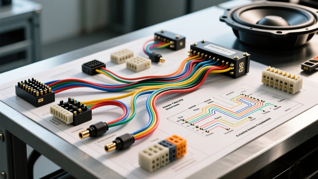
Understanding Dual Voice Coil (DVC) 4-Ohm Architecture
When designing a high-output car audio system, the 4 ohm DVC sub wiring diagram is the foundational blueprint for impedance matching and amplifier stability. Unlike Single Voice Coil (SVC) subwoofers that lock you into a fixed impedance, Dual Voice Coil (DVC) subwoofers feature two independent voice coils wound around the same cylindrical former. Each coil operates with its own set of positive and negative terminals, granting the installer the flexibility to manipulate the final load presented to the amplifier.
Before cutting a single length of speaker wire, it is critical to understand the difference between Nominal Impedance (Z) and DC Resistance (Re). According to the Consumer Technology Association (CTA-2006) mobile audio standards, a voice coil rated at 4 ohms nominal impedance will typically measure between 3.2 ohms and 3.6 ohms of DC resistance on a digital multimeter. This variance is due to the reactive nature of the voice coil as an inductor; impedance fluctuates with frequency (peaking at the resonant frequency, Fs), while resistance is the static measurement of the copper wire itself. Always verify your coil resistance with a multimeter set to the 200-ohm scale before finalizing your amplifier strap or bridging configuration.
The 4 Ohm DVC Sub Wiring Diagram Matrix
The versatility of the 4-ohm DVC architecture allows for multiple wiring topologies depending on the number of subwoofers and the stability limits of your amplifier. Below is the definitive impedance matrix for 4-ohm DVC subwoofers.
| Subwoofer Count | Wiring Topology | Final Impedance (Z) | Amplifier Requirement | Primary Use Case |
|---|---|---|---|---|
| 1x 4-Ohm DVC | Parallel | 2 Ohms | 2-Ohm Stable Mono/2-Ch | Standard daily driver builds |
| 1x 4-Ohm DVC | Series | 8 Ohms | High-Z / Tube Amps | High damping factor / SQ builds |
| 2x 4-Ohm DVC | Series-Parallel | 4 Ohms | 4-Ohm Stable Monoblock | Maximum power transfer (Standard) |
| 2x 4-Ohm DVC | All Parallel | 1 Ohm | 1-Ohm Stable Monoblock | SPL competition / High-current |
| 2x 4-Ohm DVC | All Series | 16 Ohms | High-Voltage / Pro Audio | Multi-amp linking / Line matching |
Configuration 1: Single Subwoofer Parallel (2-Ohm Load)
Wiring a single 4-ohm DVC subwoofer in parallel halves the impedance, resulting in a 2-ohm final load. This is the most common configuration for entry-level monoblock amplifiers that are rated for 500W to 1000W RMS at 2 ohms.
Physical Routing Protocol
- Run a jumper wire from the Positive (+) terminal of Coil A to the Positive (+) terminal of Coil B.
- Run a jumper wire from the Negative (-) terminal of Coil A to the Negative (-) terminal of Coil B.
- Connect your main amplifier positive speaker wire to either of the Positive terminals.
- Connect your main amplifier negative speaker wire to either of the Negative terminals.
Technical Warning: Do not use the amplifier's internal bridging strap to achieve a 2-ohm load if the manual specifies bridging is only safe for 4 ohms. Bridging a 2-channel amplifier effectively halves the impedance seen by each channel. A 2-ohm parallel subwoofer load on a bridged amp presents a 1-ohm load to the output transistors, which will trigger thermal protection or cause catastrophic MOSFET failure.
Configuration 2: Dual Subwoofers Series-Parallel (4-Ohm Load)
This is the ultimate 4 ohm DVC sub wiring diagram for enthusiasts running two subwoofers on a high-output, 4-ohm stable Class D monoblock (such as a Rockford Fosgate Power T1500-1bdCP or JL Audio 1000/1v3). Achieving a 4-ohm final load maximizes amplifier efficiency, reduces alternator strain, and minimizes heat generation in the output stage.
The Series-Parallel Execution Strategy
To achieve a 4-ohm load with two 4-ohm DVC subs, you must wire the coils on each individual subwoofer in series (yielding 8 ohms per sub), and then wire the two subwoofers to the amplifier in parallel (8 ohms || 8 ohms = 4 ohms).
- Subwoofer 1 (Series): Connect a jumper from Coil A Negative (-) to Coil B Positive (+). This leaves Coil A Positive (+) and Coil B Negative (-) as your active terminals.
- Subwoofer 2 (Series): Repeat the exact same jumper process. Connect Coil A Negative (-) to Coil B Positive (+).
- Amplifier Connection (Parallel): Run a wire from Subwoofer 1 Coil A Positive (+) to the Amplifier Positive (+) terminal.
- Run a wire from Subwoofer 2 Coil A Positive (+) to the same Amplifier Positive (+) terminal.
- Run a wire from Subwoofer 1 Coil B Negative (-) to the Amplifier Negative (-) terminal.
- Run a wire from Subwoofer 2 Coil B Negative (-) to the same Amplifier Negative (-) terminal.
By utilizing this topology, the amplifier sees a perfectly balanced 4-ohm load, ensuring both subwoofers receive identical current and maintaining optimal electrical damping factor (DF) for tight, accurate bass transient response.
Power Wire Protocols: AWG, OFC, and Current Draw
An accurate 4 ohm DVC sub wiring diagram is useless if the power delivery network cannot sustain the current draw. When calculating power wire gauge, you must account for amplifier efficiency and the vehicle's charging system voltage.
Calculating Current Draw (Ohm's Law & Efficiency)
Assume a Class D monoblock rated for 1000W RMS at 4 ohms. Class D amplifiers typically operate at 80% to 85% efficiency. To find the true current draw from the alternator:
- Formula: (RMS Wattage / Efficiency) / System Voltage = Amperage
- Calculation: (1000W / 0.80) / 14.4V = 86.8 Amps continuous draw.
According to SAE International Standard J1128 for low-tension primary automotive cable, a continuous 87A draw requires a minimum of 4 AWG Oxygen-Free Copper (OFC) wire for runs up to 15 feet. If your run exceeds 15 feet, or if you are pushing 1500W+ RMS, you must upgrade to 1/0 AWG OFC for the main battery run, stepping down via a distribution block to the amplifier.
Crucial Note on CCA vs. OFC: Never use Copper-Clad Aluminum (CCA) wire for high-current car audio applications. CCA has a 40% higher electrical resistance than pure OFC. A 4 AWG CCA cable performs equivalently to an 8 AWG OFC cable, leading to severe voltage drop at the amplifier's B+ terminal, causing clipping and premature voice coil burnout.
Terminal Preparation and Grounding Standards
Signal degradation and intermittent protection-mode triggers are almost always the result of poor termination. For the speaker wire connections to the DVC terminals, use high-quality ring terminals or spade connectors.
- Speaker Wire Gauge: Use 12 AWG OFC stranded speaker wire for runs under 10 feet. The high current associated with 1-ohm and 2-ohm loads demands thicker wire to prevent resistive losses.
- Crimping: Use a ratcheting hex-crimp tool. Soldering is acceptable but can make the wire brittle near the subwoofer's excursion point; a proper mechanical hex crimp with adhesive-lined heat shrink is the automotive industry standard for vibration resistance.
- Grounding: The amplifier ground must be tied to bare, unpainted chassis metal. Use a wire brush to remove e-coat and primer. Secure the ground ring terminal with a Grade 8 or OEM-grade zinc-flake coated bolt, torqued to the manufacturer's specification (typically 10-15 Nm for M8 bolts). Keep the ground wire under 18 inches in length.
Real-World Failure Modes and Troubleshooting
Even with a perfect 4 ohm DVC sub wiring diagram, physical and thermal variables can disrupt system performance. Here are advanced troubleshooting scenarios specific to DVC configurations:
1. Thermal Compression and Impedance Rise
As copper voice coils heat up during heavy excursion and high-power playback, their resistance increases. A coil that measures 3.4 ohms at rest can easily swell to 6.0 ohms or higher at operating temperature (Thermal Compression). In a series-wired configuration, this impedance rise can push the amplifier out of its optimal efficiency band, resulting in a noticeable drop in SPL (Sound Pressure Level) during sustained bass notes. To mitigate this, ensure your enclosure has adequate cooling vents or utilize forced-air cooling systems for SPL competition vehicles.
2. Out-of-Phase Wiring (Acoustic Cancellation)
If your dual 4-ohm DVC subwoofers are wired to the amplifier correctly, but one subwoofer is physically mounted in reverse (magnet facing inward vs. outward) without reversing its polarity wires, the subs will be 180 degrees out of phase. This causes destructive acoustic interference, resulting in a hollow sound and a massive loss of low-frequency output. Always perform a 9V battery polarity test on the final speaker wires before securing the subwoofers to the baffle.
3. Amplifier Clipping due to Alternator Sag
If you wire two 4-ohm DVC subs to a 1-ohm final load, the amplifier will attempt to pull massive current (often exceeding 150 Amps). If the vehicle's alternator cannot keep up and the system voltage drops below 12.5V, the amplifier's unregulated power supply will clip the audio signal to maintain power output. This clipped square-wave signal sends massive DC current to the voice coils, melting the copper winding and destroying the subwoofer. Upgrading the vehicle's electrical system with a High-Output alternator and Lithium-Titanate (LTO) battery cells is mandatory for 1-ohm DVC configurations.
For further verification of complex multi-subwoofer topologies, installers should consult the Rockford Fosgate Impedance Calculator to visually map out series, parallel, and series-parallel routing before cutting wires. Mastering the 4 ohm DVC sub wiring diagram ensures that your system operates safely, efficiently, and at its absolute acoustic peak.