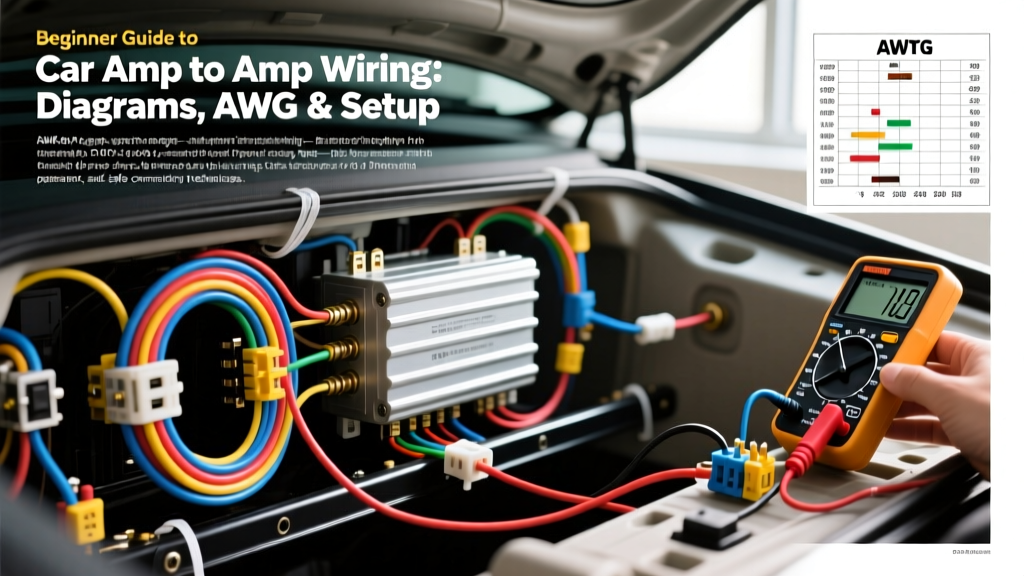
The Physics of Car Amp Wiring: Why Gauge and Material Matter
When diving into aftermarket audio, understanding the fundamentals of car amp wiring is the difference between a system that performs flawlessly and one that fries your vehicle's electrical grid. An automotive charging system operates between 13.8V and 14.4V. Amplifiers are engineered to produce their rated RMS wattage at this specific voltage. If your wiring is inadequate, voltage drop occurs, triggering the amplifier's protection circuitry or causing severe clipping that destroys subwoofer voice coils.
Before purchasing a kit, you must understand the difference between Oxygen-Free Copper (OFC) and Copper-Clad Aluminum (CCA). According to the SAE J1128 Low Tension Primary Cable Standard, conductivity is paramount. CCA wire contains an aluminum core with a thin copper wash. Aluminum has roughly 60% of the conductivity of copper, meaning a 4 AWG CCA wire will perform similarly to an 8 AWG OFC wire, leading to dangerous heat buildup and voltage starvation at the amplifier's B+ terminal.
AWG Sizing Chart: Matching Wire to Amplifier Draw
To size your power and ground wires correctly, calculate the total RMS wattage of your system. Use the formula: (Total RMS Wattage ÷ 0.5 Efficiency) ÷ 13.8V = Maximum Amperage Draw. Consult the chart below for OFC wire requirements based on run length from the battery to the amplifier.
| Total RMS Wattage | Max Current Draw (@ 13.8V) | Run: 0-10 ft (OFC) | Run: 10-20 ft (OFC) |
|---|---|---|---|
| Up to 500W | ~60 Amps | 8 AWG | 4 AWG |
| 500W - 1000W | ~120 Amps | 4 AWG | 2 AWG |
| 1000W - 1500W | ~180 Amps | 2 AWG | 1/0 AWG |
| 1500W+ | 200+ Amps | 1/0 AWG | 2/0 AWG |
Step-by-Step Power and Ground Execution
1. Battery Connection and Inline Fusing
Never wrap power wire around a battery post. Use a marine-grade dual battery terminal or a dedicated ANL fuse distribution block. The National Electrical Code and automotive best practices dictate that the main inline fuse must be located within 18 inches of the positive battery post. This protects the vehicle from a dead short in the event of a collision or chafed firewall grommet. For a 150A system, use an ANL fuse with an M8 set screw, torqued to approximately 4-5 Nm to prevent arcing.
2. Firewall Penetration
Locate the factory rubber wiring grommet on the firewall. Never use a metal drill bit near factory harnesses. Instead, use a plastic trim awl to pierce a small cross-slit in the rubber, feed the power wire through, and seal it with marine-grade silicone to prevent carbon monoxide and water intrusion into the cabin.
3. Establishing a True Chassis Ground
The ground wire should be the same AWG as the power wire and kept as short as possible (under 3 feet). Locate a factory seatbelt anchor or structural chassis bolt. You must sand away the factory E-coat, paint, and primer down to bare, shiny steel. Use a closed-loop 3/8' ring terminal, crimped with a hex-crimper (never use hammer-crimps for high-amperage audio circuits). Coat the terminal in dielectric grease after tightening to prevent galvanic corrosion. As noted by the experts at Basic Car Audio Electronics, over 80% of amplifier protection faults and alternator whine issues stem from poor chassis grounds.
Signal Routing and the Remote Turn-On Circuit
RCA cables carry low-voltage (typically 2V to 5V) unbalanced audio signals. They are highly susceptible to Electromagnetic Interference (EMI) from the alternator, ignition coils, and fuel pump modules. To prevent alternator whine, strictly adhere to the split-routing rule: run your power and ground wires down the driver's side rocker panel, and route your RCA and speaker wires down the passenger side. If they must cross, ensure they intersect at a strict 90-degree angle.
The Remote Turn-On (REM) Wire
The 18 AWG blue/white wire triggers the amplifier's internal relay. In standard ISO 10487 head unit harnesses, this connects to Pin 5 (Auto Antenna / Amp Turn-On). This circuit is typically limited to 300mA. If you are powering multiple amplifiers, a DSP, and a cooling fan, do not daisy-chain them directly to the head unit's remote lead. Instead, use the head unit's remote wire to trigger a standard Bosch-style 12V automotive relay (Pins 85 and 86 for the coil, Pin 30 for 12V constant, and Pin 87 for the switched 12V output to your amps).
When to Perform the 'Big 3' Wiring Upgrade
If your car amp wiring setup exceeds 1500W RMS, or if you notice your headlights dimming heavily on bass transients, your factory charging system wiring is likely bottlenecking the current. The factory alternator-to-battery wire is often undersized (sometimes as small as 6 AWG or 8 AWG on economy vehicles) to save manufacturing costs. Performing the 'Big 3' upgrade involves replacing or supplementing three critical factory cables with 1/0 AWG OFC wire:
- Alternator Positive to Battery Positive: This allows the alternator to deliver maximum current directly to the battery and audio distribution blocks without voltage drop.
- Battery Negative to Chassis: Improves the overall return path for all vehicle electronics.
- Engine Block to Chassis: Ensures the alternator casing and engine block are properly grounded, which is vital since the alternator generates the AC current that is rectified to DC for your amplifiers.
When upgrading these lines, always disconnect the negative battery terminal first, and ensure you use heavy-duty 3/8' or 5/16' ring terminals with heat-shrink tubing to prevent under-hood moisture corrosion.
Speaker Wire Routing and Termination Standards
While power wire gets all the attention, proper speaker wire termination is equally vital for maintaining damping factor and audio clarity. For runs under 15 feet, 16 AWG OFC speaker wire is sufficient. For subwoofer runs or longer distances to rear deck speakers, step up to 12 AWG. Never use the factory 22 AWG speaker wire for aftermarket amplifiers, as its high resistance will severely degrade the amplifier's damping factor, resulting in 'muddy' or loose bass response.
At the amplifier terminals, use insulated spade connectors rather than bare wire. Bare wire strands can easily break off, stray into adjacent channels, and cause a dead short that will instantly blow the amplifier's internal output transistors. Crimp the spades with a ratcheting crimper and apply a small dab of hot glue or conformal coating over the set screw to prevent vibration from loosening the connection over time.
Troubleshooting Common Installation Faults
| Symptom | Diagnostic Check | Resolution |
|---|---|---|
| Alternator Whine (pitch changes with RPM) | Ground loop or RCA running parallel to power wire. | Verify amp ground resistance is <0.1 ohms. Reroute RCA cables away from B+ wire. |
| Amp goes into Protect Mode at high volume | Voltage drop at B+ terminal or impedance mismatch. | Measure B+ and REM at amp terminals with a DMM while playing bass. If voltage drops below 11V, upgrade power wire or add a capacitor/lithium battery. |
| No Audio, Amp Power Light is OFF | Blown inline fuse or broken remote turn-on circuit. | Check ANL fuse continuity. Test head unit Pin 5 for 12V output when powered on. |
| Subwoofer Chuffing / Distortion | Clipping due to improper gain staging. | Set head unit EQ to flat. Use an oscilloscope or a 50Hz/1kHz test tone to set amp gain to match the head unit's pre-out voltage. |
Mastering car amp wiring requires patience and adherence to electrical standards. By investing in true OFC wire, executing bare-metal grounds, and respecting signal isolation, your car audio system will deliver clean, reliable power for years to come. For further reading on harness integration, consult Crutchfield's Amplifier Installation Guide for vehicle-specific wiring diagrams.