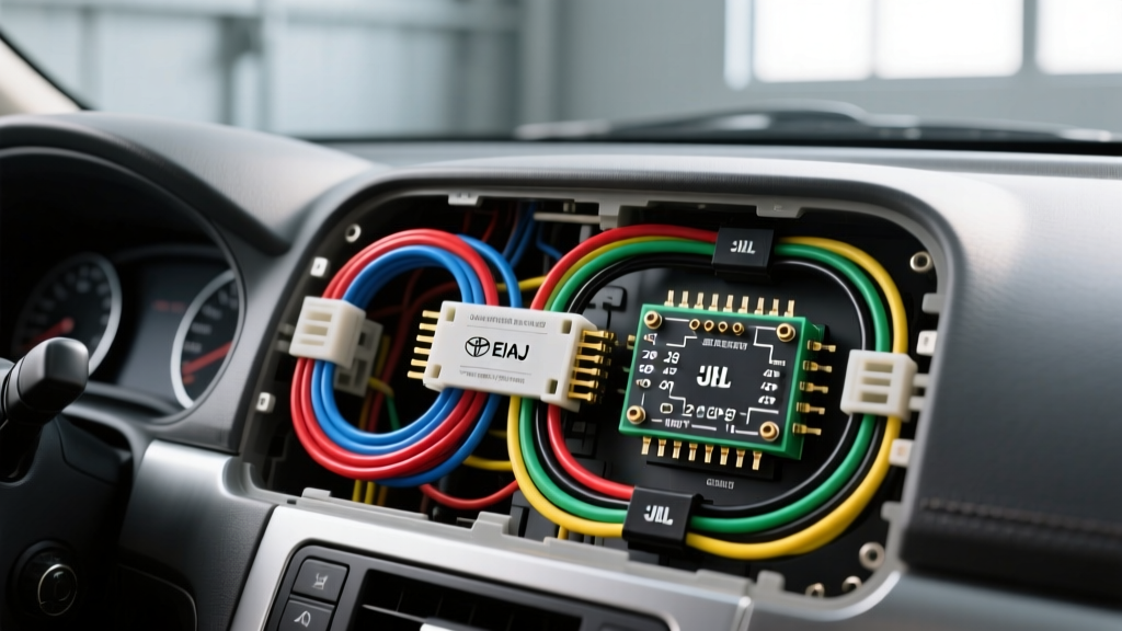
Decoding the Toyota Stereo Wiring Diagram: A Technical Reference
Interpreting a Toyota stereo wiring diagram requires more than just matching wire colors; it demands a fundamental understanding of Toyota’s proprietary connector standards, impedance matching, and multiplex communication networks. Unlike legacy domestic vehicles that relied on standardized GM/Chrysler color codes, Toyota utilizes a mix of EIAJ (Electronic Industries Association of Japan) and modern JST (Japan Solderless Terminal) connectors. Whether you are bypassing a factory JBL amplified system or integrating a 2-DIN aftermarket head unit into a modern CAN-bus architecture, misinterpreting the pinout can lead to blown output ICs, parasitic battery drains, or severe ECU communication faults.
The Evolution of Toyota Head Unit Connectors
Before cutting or splicing, you must identify the specific connector generation on your vehicle's harness. Toyota has transitioned through three primary harness architectures over the last three decades:
- Pre-2003 (10-Pin & 14-Pin EIAJ): Found in older Tacomas, Camrys, and Corollas. These feature simple analog power, ground, and speaker outputs with no data bus integration.
- 2003–2015 (20-Pin & 24-Pin Dual Harness): The most common aftermarket adaptation point. This era introduced the 20-pin primary power/speaker block and a separate 14-pin or 24-pin secondary block for steering wheel controls (SWC), reverse cameras, and auxiliary inputs.
- 2016–Present (28-Pin JST E-Series): Modern Tundras, RAV4s, and Camrys utilize a high-density 28-pin JST connector. This harness consolidates power, speakers, and high-speed CAN-bus data lines into a single plug, requiring specialized interface modules to prevent network faults.
Standard 20-Pin Toyota Stereo Wiring Diagram Reference
The following table details the industry-standard 20-pin EIAJ connector found in the majority of non-JBL Toyota applications from 2004 to 2015. Always verify with a digital multimeter (DMM) before making hardwired connections, as mid-year production changes can alter secondary wire tracer colors.
| Pin | Wire Color (Base/Tracer) | Function | AWG Rating | Technical Notes |
|---|---|---|---|---|
| 1 | Blue / Yellow Stripe | +12V Constant (BATT) | 16-18 AWG | Supplies ECU memory and clock. Draw limit: 5A. |
| 2 | Gray | +12V Accessory (ACC) | 16-18 AWG | Triggered via ignition switch. Do not use for amp remote turn-on. |
| 3 | Brown | Chassis Ground (GND) | 16 AWG | Must read < 0.05Ω to chassis. Do not rely on dash bracing for ground. |
| 4 | Green / White Stripe | Illumination (+) | 20-22 AWG | Variable voltage (0-12V) tied to headlight dimmer switch. |
| 5 | Blue / Black Stripe | Power Antenna / Amp Remote | 20 AWG | Outputs +12V only when Radio/Tuner source is active. |
| 7 | Pink | Front Left Speaker (+) | 20 AWG | Verify phase with a 9V battery pop-test if factory colors are faded. |
| 8 | Purple | Front Left Speaker (-) | 20 AWG | Floating ground system. Do NOT tie to chassis ground. |
| 9 | Light Green | Front Right Speaker (+) | 20 AWG | Standard 4-ohm impedance. |
| 10 | Blue | Front Right Speaker (-) | 20 AWG | Keep away from CAN-bus twisted pairs to avoid EMI. |
| 11 | Black | Rear Left Speaker (+) | 20 AWG | Often shares conduit with rear lighting harness. |
| 12 | Yellow | Rear Left Speaker (-) | 20 AWG | Check for continuity to ground; a short indicates pinched wire in door boot. |
| 13 | Red | Rear Right Speaker (+) | 20 AWG | Standard 4-ohm impedance. |
| 14 | White | Rear Right Speaker (-) | 20 AWG | Ensure proper crimping; Toyota OEM pins use a specific JST taper. |
Note: Pins 6, 15-20 are typically reserved for CD changers, secondary illumination, or mute triggers depending on the specific trim level. Reference the Crutchfield Toyota Wiring Database for year-specific anomalies.
Decoding the JBL Premium Audio System Architecture
When a Toyota stereo wiring diagram indicates a JBL Synthesis or JBL Premium audio system, the standard 20-pin rules are immediately invalidated. In JBL-equipped vehicles (e.g., Tundra, Sequoia, Avalon), the head unit acts solely as a pre-amplifier and data controller. The actual 24W x 4 (or higher) amplification occurs in a factory amplifier typically located under the passenger seat, behind the dash, or in the rear quarter panel.
The Impedance Mismatch Problem
Toyota’s JBL systems utilize low-impedance speakers, typically rated at 2 ohms for the front and 4 ohms for the rear. If you wire an aftermarket 4-ohm speaker directly to the factory JBL amplifier outputs, the amp will see a higher load, resulting in a 3dB to 6dB loss in output volume and altered frequency response. Conversely, wiring a 2-ohm aftermarket subwoofer to a standard non-JBL Toyota head unit will overheat the internal MOSFETs and trigger the unit's thermal protection circuit, shutting down the audio output entirely.
Bypassing the Factory JBL Amplifier
To integrate an aftermarket head unit and amplifier into a JBL vehicle, you must bypass the factory amp. This requires running new 14 AWG or 16 AWG speaker wire from your aftermarket DSP or amplifier directly to the door speakers, bypassing the factory wiring entirely. Alternatively, use a specialized JBL bypass harness (such as those from PAC Audio or Axxess) that includes built-in line output converters (LOCs) and load resistors to satisfy the factory head unit's diagnostic checks.
CAN-Bus Integration in 28-Pin E-Series Connectors
For 2016 and newer Toyotas, the wiring diagram shifts from analog triggers to digital multiplexing. The 28-pin JST E-Series connector houses the vehicle's high-speed CAN-bus network. The stereo is no longer turned on by a simple 12V ACC wire; instead, it wakes up when it detects a specific CAN-bus message broadcast by the Body Control Module (BCM).
- Pin 15 (Pink): CAN-High (CAN-H). Dominant state: 3.5V, Recessive state: 2.5V.
- Pin 16 (Purple): CAN-Low (CAN-L). Dominant state: 1.5V, Recessive state: 2.5V.
Critical Warning: The factory Toyota radio contains a 120-ohm termination resistor for the infotainment CAN-bus branch. If you remove the factory radio and install an aftermarket unit without a CAN-bus interface module that emulates this resistor, the entire CAN network will experience signal reflection. This leads to U-codes (e.g., U0199 - Lost Communication with Door Control Module), erratic dashboard behavior, and a parasitic battery drain because the network never enters "sleep" mode. Always utilize a data bypass module (like the PAC RP3.2-TY1 or iDatalink Maestro RR) that maintains proper network termination and translates CAN-bus sleep commands into a physical 12V remote turn-on signal for your aftermarket gear.
Diagnostic Decision Tree: Common Installation Failure Modes
Use this structured diagnostic approach when troubleshooting Toyota stereo installations based on real-world failure modes documented in PAC Audio Technical Documentation and SAE J1939 CAN-Bus Standards.
Symptom 1: Head Unit Powers On, But No Audio & Steering Wheel Controls Fail
- Cause A: Missing CAN-bus interface or blown CAN-bus data line fuse.
- Fix: Verify CAN-H and CAN-L continuity at the 28-pin connector. Ensure the interface module is flashed with the correct Toyota firmware via USB.
- Cause B (JBL Systems): Factory amplifier not receiving wake-up signal.
- Fix: Check the Amp Turn-On wire (usually Blue/White) at the factory amp harness. Ensure the interface module is configured to output +12V on the amp remote wire upon receiving the CAN wake-up command.
Symptom 2: Severe Alternator Whine in JBL Equipped Vehicles
- Cause: Ground loop induced by high-level speaker wire interference or improper LOC grounding.
- Fix: Do not ground your Line Output Converter (LOC) to the factory JBL amp chassis ground, which is often tied to a noisy multiplex ground bus. Run a dedicated 12 AWG ground wire for the LOC/DSP directly to a clean, unpainted chassis bolt in the cabin, ensuring resistance is strictly < 0.02Ω.
Symptom 3: Parasitic Battery Drain (0.5A+ Draw After Sleep)
- Cause: Aftermarket head unit or interface module failing to detect the CAN-bus "Sleep" command due to missing termination resistance.
- Fix: Measure the voltage between CAN-H and CAN-L with the vehicle locked and sleeping. If the differential voltage does not drop to 0V (both lines resting at 2.5V), the module is keeping the bus awake. Install a PAC TRUNK-LOC or verify the OEM 120-ohm termination resistor is intact within the interface harness.
By treating the Toyota stereo wiring diagram not just as a color-matching guide, but as a blueprint of the vehicle's electrical and data architecture, you ensure reliable, high-fidelity audio integration without compromising the vehicle's sensitive onboard electronics.