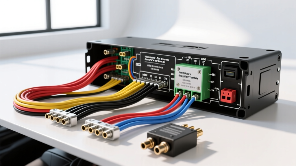
Why Your Head Unit Needs a Car Stereo Relay
When upgrading your vehicle's audio system, adding multiple amplifiers, a digital signal processor (DSP), and line drivers is standard practice. However, a critical bottleneck exists in your dashboard: the head unit's remote turn-on (REM) circuit. Most aftermarket stereos from brands like Pioneer, Kenwood, and Alpine limit their internal REM switching transistor to a maximum of 300mA to 500mA. While a single amplifier's remote input draws a negligible 20mA to 40mA, daisy-chaining three amplifiers, a DSP, and a Bluetooth controller can easily exceed 400mA. Exceeding this threshold will overheat and permanently destroy the head unit's internal PCB trace or switching transistor.
The solution is installing a car stereo relay to handle the current distribution. By using the head unit's low-current REM signal merely to trigger the relay's electromagnetic coil, you can safely distribute a robust, high-current 12V+ signal from the battery to all your aftermarket audio components without risking your source unit. According to the Crutchfield Amplifier Installation Guide, utilizing a relay for multi-amp systems is a mandatory best practice for long-term reliability.
Standard Bosch ISO Mini Relay Pinout & Specifications
The automotive industry standard for this application is the Bosch-style ISO mini relay (typically rated for 30/40 Amps). While you will not be pushing 30 Amps through the remote turn-on wires, these relays are ubiquitous, inexpensive, and highly reliable. Below is the standard 5-pin configuration mapped to your car audio wiring.
| Pin Number | Internal Function | Car Audio Application | Recommended Wire Gauge | Standard Wire Color |
|---|---|---|---|---|
| 85 | Coil Ground | Chassis Ground | 18 AWG | Black |
| 86 | Coil Power (Trigger) | Head Unit REM (Blue/White) | 18 AWG | Blue/White |
| 30 | Common Input | 12V+ Constant (Fused) | 14 AWG or 12 AWG | Yellow |
| 87 | Normally Open (NO) Output | To Amplifiers' REM Terminals | 18 AWG | Blue/White |
| 87a | Normally Closed (NC) | Not Used (Tape off) | N/A | N/A |
Tools and Materials Required
- Relay: Standard 12V Bosch-style 5-pin relay (SPDT).
- Diode: 1N4004 or 1N4007 rectifier diode (crucial for flyback protection).
- Wire: 18 AWG stranded copper primary wire (Blue/White, Black, Red).
- Fuse: Inline ATC fuse holder with a 5A or 10A blade fuse.
- Connectors: Nylon female quick-disconnect terminals (for relay pins), butt connectors, and ring terminals.
- Tools: Wire strippers, crimping tool, soldering iron, heat gun, adhesive-lined marine heat shrink, and a digital multimeter.
Step-by-Step Car Stereo Relay Installation
Step 1: Identify and Verify the Remote Turn-On Source
Before cutting any wires, use a digital multimeter to verify your head unit's remote output. Locate the Blue/White wire on the aftermarket stereo harness. This is the dedicated "System Remote Control" wire. Warning: Do not use the solid Blue wire. The solid Blue wire is typically reserved for a power antenna and will turn off when you switch the radio from AM/FM to CD or Bluetooth, causing your amplifiers to shut off and produce a loud popping noise. As outlined in Haynes Automotive Electrical Basics, verifying circuit behavior with a multimeter prior to integration prevents catastrophic diagnostic headaches later.
Step 2: Wire the Electromagnetic Coil (Pins 85 & 86)
The coil requires minimal current (usually around 150mA) to create the magnetic field that pulls the internal switch closed.
- Crimp a female quick-disconnect terminal to a length of 18 AWG Blue/White wire and attach it to Pin 86.
- Connect the other end of this Blue/White wire to the head unit's Blue/White REM output using a solder-and-heat-shrink connection.
- Crimp a female quick-disconnect to an 18 AWG Black wire and attach it to Pin 85.
- Route the Black wire to a clean, unpainted metal surface on the vehicle's chassis. Sand away any paint or rust, and secure it using a ring terminal and an OEM 10mm bolt to ensure a zero-resistance ground.
Step 3: Install Flyback Diode Protection (Critical Step)
When the head unit turns off and cuts power to the relay coil (Pin 86), the collapsing magnetic field inside the coil generates a high-voltage reverse spike (inductive kickback). In modern vehicles with sensitive Body Control Modules (BCMs) or delicate aftermarket head units, this spike can travel backward through the REM wire and fry the stereo's microcontroller.
To prevent this, solder a 1N4004 diode across Pins 85 and 86. The silver stripe on the diode body must point toward Pin 86 (the 12V+ trigger side). This creates a closed loop that safely dissipates the inductive spike back into the coil, protecting your expensive electronics. This adherence to SAE J284 standards for automotive relay inductive load suppression is what separates professional installers from amateurs.
Step 4: Wire the High-Current Switch (Pins 30 & 87)
Now you will wire the circuit that actually powers your amplifiers' remote terminals.
- Connect an 18 AWG Yellow wire to Pin 30. Route this wire to a 12V+ Constant power source (such as the main battery feed or the head unit's Yellow constant wire). You must install an inline 5A fuse within 6 inches of the power tap point.
- Connect an 18 AWG Blue/White wire to Pin 87. This is your new, high-current REM output.
- Run the Pin 87 wire to a distribution block or splice it into the REM terminals of your amplifiers, DSP, and line drivers. Because this signal is now sourced directly from the battery (via Pin 30), it will provide a rock-solid 12V+ to every component, eliminating the voltage drop that causes amplifiers to enter protect mode or fail to trigger.
- Wrap the unused Pin 87a terminal with electrical tape to prevent accidental short circuits.
Troubleshooting Common Relay Clicking & Failure Modes
Even with meticulous wiring, issues can arise. Use this diagnostic matrix to identify and resolve car stereo relay problems.
Symptom: Relay Clicks, But Amplifiers Do Not Turn On
- Cause 1: Missing 12V+ at Pin 30. The inline fuse may be blown, or the tap into the constant 12V source is faulty. Use a multimeter to check for 12.6V at Pin 30 with the car off.
- Cause 2: Poor connection at Pin 87 output. Ensure the wire traveling to the amplifiers is securely crimped and not pinched under interior trim panels.
Symptom: Relay Rapidly Chatters or Buzzes
- Cause 1: High resistance on the ground circuit (Pin 85). If the chassis ground is painted or loose, the coil cannot build sufficient magnetic force to fully seat the internal switch, causing it to bounce. Sand the ground point to bare metal.
- Cause 2: Voltage drop on the trigger wire (Pin 86). If the head unit's REM wire is damaged or overloaded, it may only be sending 8V to the coil. A standard 12V relay requires at least 9V to engage reliably.
Symptom: Head Unit Shuts Off or Displays "Error" When Turning Off
- Cause: Missing or incorrectly oriented flyback diode. The inductive voltage spike is back-feeding into the head unit's logic board, causing a brownout or microcontroller reset. Verify the 1N4004 diode is installed with the stripe facing Pin 86.
Remote Turn-On vs. Main Power Switching
The guide above covers using a car stereo relay for remote turn-on distribution (low current, 18 AWG). However, some high-end competition head units or vintage radios lack a dedicated REM wire entirely. In these cases, the relay is used to switch the main accessory power (Red wire) to the stereo itself.
If you are switching main stereo power, you must upgrade your wire gauges. Pins 30 and 87 must be wired with 12 AWG or 10 AWG wire to handle the 15A to 25A current draw of the head unit and its internal amplifiers. The fuse on Pin 30 should be upgraded to 20A or 25A, and the ground on Pin 85 should be upgraded to 12 AWG. Never use 18 AWG wire for main power switching, as the resistance will cause severe voltage drop, leading to head unit clipping and thermal damage to the relay's internal contacts.
By properly integrating a car stereo relay into your audio system, you ensure instantaneous, synchronized turn-on for all components while completely isolating your delicate source unit from high-current demands and inductive spikes. Always double-check your pinouts, solder your connections, and protect your circuits with proper fusing and diodes.