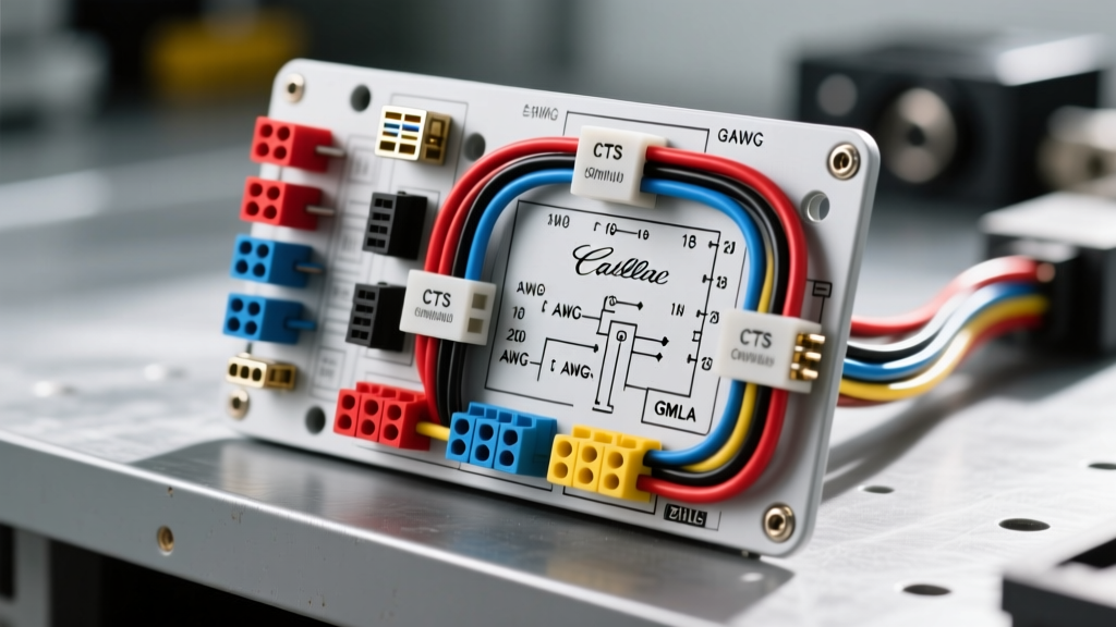
GM Cadillac Bose Audio Architecture Overview
When tackling a custom audio build or diagnostic repair in a luxury GM vehicle, locating an accurate factory radio wiring Cadillac Bose amp wiring diagram is only the first step. Unlike standard base-model stereos that output high-level speaker signals directly from the head unit, Cadillac models equipped with the Bose premium audio system (specifically the 2008-2014 CTS, STS, and SRX platforms) utilize a distributed amplification architecture. The factory radio acts primarily as a source unit, display interface, and volume controller. It sends low-level analog differential signals to a remote, multi-channel Bose amplifier located in the trunk or under the rear deck.
Understanding this architecture is critical for aftermarket integration. Attempting to use a standard high-level to low-level line output converter (LOC) at the back of the factory radio will result in severe distortion, as the signals are already at line-level (typically 2V to 4V RMS). Furthermore, the Bose amplifier does not utilize a traditional 12V remote turn-on wire. Instead, it relies on the GMLAN (Global Manufacturing Local Area Network) serial data bus to receive a wake-up command from the Body Control Module (BCM). For deeper insights into vehicle-specific integration, the Crutchfield Vehicle Wiring Database remains an essential reference for harness compatibility.
Head Unit to Amplifier Input Pinout (X2 Connector)
The connection between the Cadillac head unit and the Bose amplifier is facilitated by the X2 low-level audio connector. These wires carry the pre-amplified analog signals. Because they are low-voltage, they are highly susceptible to Electromagnetic Interference (EMI) from the vehicle's alternator and high-voltage ignition coils. GM routes these wires through the center console, strictly separating them from the main 12V power harness to prevent alternator whine.
| Pin | Wire Color | Function | Signal Type |
|---|---|---|---|
| 1 | Light Blue | Left Front Audio (+) | Low-Level Analog |
| 2 | Dark Blue | Left Front Audio (-) | Low-Level Analog |
| 3 | Light Green | Right Front Audio (+) | Low-Level Analog |
| 4 | Dark Green | Right Front Audio (-) | Low-Level Analog |
| 5 | Light Brown | Left Rear Audio (+) | Low-Level Analog |
| 6 | Dark Brown | Left Rear Audio (-) | Low-Level Analog |
| 7 | Light Purple | Right Rear Audio (+) | Low-Level Analog |
| 8 | Dark Purple | Right Rear Audio (-) | Low-Level Analog |
Note: If integrating an aftermarket DSP (Digital Signal Processor), you can tap these wires directly at the head unit or at the amplifier input, provided you use shielded twisted-pair cabling for any extended runs.
Bose Amplifier Output Matrix (X3 32-Pin Connector)
The X3 connector is the high-level output stage of the Bose amplifier, sending amplified power to the individual door and rear deck speakers. The factory Bose speakers in Cadillac vehicles are often proprietary 2-ohm or 4-ohm neodymium drivers. When replacing the factory amplifier but retaining the Bose speakers, you must ensure your aftermarket amplifier is stable at 2 ohms per channel, or the internal protection circuitry will trigger thermal shutdown during high-volume operation.
| Pin | Wire Color | Function | AWG |
|---|---|---|---|
| 12 | Light Green | Left Front Speaker (+) | 18 AWG |
| 13 | Dark Green | Left Front Speaker (-) | 18 AWG |
| 14 | Light Blue | Right Front Speaker (+) | 18 AWG |
| 15 | Dark Blue | Right Front Speaker (-) | 18 AWG |
| 16 | Light Brown | Left Rear Speaker (+) | 18 AWG |
| 17 | Dark Brown | Left Rear Speaker (-) | 18 AWG |
| 18 | Light Purple | Right Rear Speaker (+) | 18 AWG |
| 19 | Dark Purple | Right Rear Speaker (-) | 18 AWG |
Power, Ground, and GMLAN Data Specifications
The most common point of failure and confusion when referencing a Cadillac Bose amp wiring diagram is the power and data distribution. The amplifier requires a robust ground connection to the vehicle chassis. The factory ground bolt (typically an M8 flange bolt) must be torqued to 20 Nm to ensure a zero-resistance path. A poor ground will manifest as a clipping subwoofer or severe thermal tracking inside the Bose amp ICs.
Furthermore, the GMLAN bus is a differential serial data network. According to the Melexis GMLAN Physical Layer Application Note, the bus operates at specific voltage thresholds (typically 0V to 5V for Single Wire CAN, or differential swings for High-Speed CAN depending on the exact model year and module). To generate a 12V remote turn-on signal for an aftermarket amplifier, you must use a GMLAN data bus interface module (such as the PAC RP5-GM31 or Axxess XSVI-2105) that 'sniffs' the data packets and triggers a relay when the 'Audio On' command is broadcast by the BCM.
| Circuit | Wire Color | Function | Specification |
|---|---|---|---|
| B+ | Red / White Stripe | Constant Battery Power | 10 AWG (Fused at 30A) |
| GND | Black / White Stripe | Chassis Ground | 10 AWG (M8 Bolt, 20 Nm) |
| GMLAN High | Green | Serial Data Bus (+) | 22 AWG Shielded |
| GMLAN Low | Green / White | Serial Data Bus (-) | 22 AWG Shielded |
Active Noise Cancellation (ANC) Defeat Protocol
A critical, often overlooked aspect of Cadillac Bose systems is the Active Noise Cancellation (ANC). The vehicle utilizes microphones embedded in the headliner to sample low-frequency engine drone. The Bose amplifier then generates an inverted phase signal through the factory subwoofer and door speakers to cancel the noise. If you bypass the Bose amplifier, replace the speakers, or alter the acoustic phase of the cabin, the ANC system will lose its reference point. This results in a catastrophic low-frequency feedback loop (a loud, rhythmic howling or booming sound) that can instantly destroy aftermarket tweeters and subwoofers.
Methods for ANC Defeat:
- Physical Disconnect: Locate the ANC module (often integrated into the Bose amp or mounted behind the rear headliner) and disconnect the microphone harness.
- Software Disable: Use a GM GDS2/Tech2 diagnostic tool to access the Radio or Amplifier module configuration and set 'Active Noise Cancellation' to 'Not Present'.
- Aftermarket Bypass Harness: Utilize a dedicated GM ANC defeat dongle that plugs into the data bus and spoofs the microphone signal, tricking the BCM into believing the cabin is silent.
Wire Routing and EMI Shielding Best Practices
When extending or modifying the wiring based on your Cadillac Bose amp wiring diagram, strict adherence to automotive EMI shielding standards is required. The SAE International Automotive Network Standards dictate that low-voltage data and analog audio lines must maintain a minimum clearance of 150mm from high-current 12V power cables and ignition coil harnesses. If crossing is unavoidable, the wires must intersect at a strict 90-degree angle to minimize inductive coupling. Always use copper-braided shielded cables for any custom RCA or low-level analog runs, and ensure the shield drain wire is grounded at the source (head unit) only, to prevent ground loops.