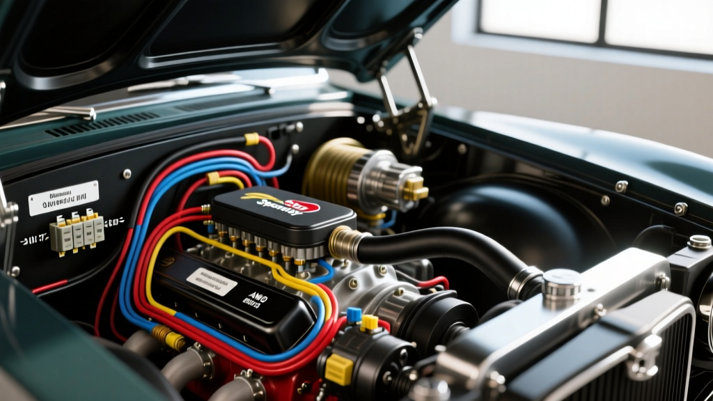
Why Ditch the OEM Loom for a Speedway Universal Wiring Harness?
When performing an upgrade and modification project on a classic hot rod, street rod, or custom build, retaining the original 50-year-old electrical system is a liability. Factory wiring from the 1960s and 70s typically utilizes PVC insulation that becomes brittle, cracks, and exposes copper to moisture and short circuits. Furthermore, vintage harnesses lack the circuit capacity to support modern upgrades like electric cooling fans, electronic fuel injection (EFI), and high-output halogen or LED lighting.
Installing a Speedway universal wiring harness—typically a 14-circuit or 21-circuit universal kit—provides a clean, color-coded, and fully fused foundation. These kits utilize modern cross-linked polyethylene (XLPE) insulated wire, centralized ATO/Maxi fuse blocks, and pre-terminated bulkhead connectors. This guide details the technical specifications, routing strategies, and termination best practices required to execute a flawless harness upgrade in your project vehicle.
Anatomy of the 21-Circuit Fuse Block Allocation
The core of the Speedway universal wiring harness is the centralized fuse block. Proper circuit allocation ensures that high-draw accessories do not starve sensitive electronics of voltage. Below is a standard allocation map for a 21-circuit universal hot rod harness, detailing the factory wire colors, American Wire Gauge (AWG) sizes, and recommended fuse ratings.
| Circuit ID | Wire Color | AWG Size | Destination / Function | Max Fuse Rating |
|---|---|---|---|---|
| C1 | Red | 10 AWG | Headlight Power Feed (via Relay) | 30A |
| C2 | White | 12 AWG | Headlight High Beam Feed | 20A |
| C3 | Yellow | 14 AWG | Ignition Switch (BATT Feed) | 15A |
| C4 | Purple | 14 AWG | Starter Solenoid 'I' Terminal (Bypass) | 15A |
| C5 | Brown | 14 AWG | Tail, Parking, and Marker Lights | 15A |
| C6 | Green | 14 AWG | Left Rear Stop / Turn Signal | 15A |
| C7 | Dark Green | 14 AWG | Right Rear Stop / Turn Signal | 15A |
| C8 | Orange | 12 AWG | Horn Relay / Dome Light Feed | 20A |
| C9 | Blue | 12 AWG | Wiper Motor / Washer Pump | 20A |
| C10 | Pink | 14 AWG | Radio / Dash Accessories (IGN Switched) | 10A |
| C11 | Gray | 18 AWG | Instrument Panel Illumination | 5A |
Note: Always verify the specific color code legend included with your exact Speedway harness kit, as revisions can occasionally alter secondary wire trace colors.
SAE Standards and Wire Insulation Specifications
Universal harness kits sourced from reputable manufacturers adhere to SAE J1128 standards for low-tension primary automotive cables. The wire utilized in these Speedway-compatible kits is typically GXL (General Cross-Linked) or TXL (Thin-wall Cross-Linked).
Unlike vintage PVC wire which melts at roughly 105°C, GXL and TXL insulation can withstand continuous operating temperatures up to 125°C. This is critical in tight engine bays where headers and exhaust manifolds radiate intense heat. The thin-wall construction of TXL also reduces the overall diameter and weight of the harness, making it significantly easier to route through classic firewall bulkheads and concealed kick panels without compromising the copper stranding's current-carrying capacity.
The Critical Role of Chassis Grounding
The most common point of failure in any hot rod modification project is inadequate grounding. A Speedway universal wiring harness will only perform as well as its ground paths. According to the Mad Electrical Grounding Guide, relying on rusty body bolts or painted chassis tabs for high-amperage returns will result in severe voltage drop, dim lights, and erratic ECU behavior.
Grounding Best Practices for Custom Builds
- Engine-to-Chassis Strap: Use a minimum 4 AWG braided copper ground strap connecting the engine block (near the starter or alternator bracket) directly to the chassis frame rail. Braided wire is mandatory here to withstand engine torque roll and vibration without snapping.
- Battery-to-Chassis: Run the main 1/0 AWG or 2 AWG battery negative cable directly to a dedicated, bare-metal chassis grounding lug near the starter motor.
- Body and Bed Grounds: Run 10 AWG or 12 AWG ground wires from the chassis to the firewall, doors, and truck beds. Use ring terminals secured with star washers to bite through paint and primer, ensuring a zero-resistance connection to bare steel.
- Harness Ground Bus: The Speedway kit includes a dedicated ground bus bar or heavy black ground wires. These must be terminated to a central, clean chassis point under the dash, not simply bolted to a random sheet metal screw.
Routing, Looming, and Termination Techniques
Proper routing protects the harness from mechanical abrasion and thermal damage. When routing the main chassis harness through the firewall, use a dedicated rubber or neoprene firewall pass-through grommet. Never drill a hole in the firewall and push bare wires through; the sharp steel edge will slice through the GXL insulation and cause a dead short against the chassis.
Conduit Selection
While split-loom plastic tubing is common in OEM applications, it traps moisture and looks out of place in a high-end hot rod. For under-dash and interior routing, use expandable braided PET sleeving (Techflex). For under-hood applications, use non-adhesive harness wrapping tape (like Tesa 51036) or high-temp fiberglass sleeving near exhaust headers. Maintain a minimum 6-inch clearance from all exhaust components.
Terminal Crimping vs. Soldering
Automotive electrical experts strongly advise against soldering wire connections in high-vibration environments. Solder wicks into the wire strands via capillary action, creating a rigid, brittle stress point that will eventually snap under engine vibration. Instead, use open-barrel F-crimp terminals (such as Delphi 280 or Packard 56 series) with a dedicated ratcheting crimp tool. Finish the connection with dual-wall, adhesive-lined heat shrink tubing to seal out moisture and prevent galvanic corrosion.
Upgrading High-Draw Circuits with Relays
While the Speedway universal harness provides switched power to the headlight switch, running 10 AWG headlight feeds directly through a vintage dashboard switch will melt the switch contacts over time. You must upgrade high-draw circuits using Bosch-style 4-pin or 5-pin relays.
Headlight Relay Upgrade Wiring
- Pin 30 (Power In): Connect directly to the battery positive or main starter stud via a 10 AWG wire with an inline 30A Maxi-fuse.
- Pin 86 (Switched Trigger): Connect to the harness headlight output wire (the wire that originally fed the headlights directly).
- Pin 85 (Ground): Connect to a clean chassis ground point.
- Pin 87 (Power Out): Run a new 10 AWG or 12 AWG wire directly to the headlight high/low beam connectors.
This setup ensures the heavy electrical load bypasses the dashboard switch entirely, resulting in maximum voltage delivery to the headlights and significantly extended switch lifespan.
Troubleshooting Common Post-Install Gremlins
Even with a premium harness, modification projects often encounter electrical anomalies. Use this decision tree to diagnose common issues after firing up your newly wired hot rod.
Symptom: Alternator is Not Charging the Battery
- Cause A: Missing exciter wire. If using a classic Delco 10SI or 12SI 3-wire alternator, the #1 terminal requires a 14 AWG exciter wire connected to an ignition-switched 12V source (often routed through a dash indicator bulb or a 10A resistor wire). Without this signal, the internal voltage regulator will not turn on.
- Cause B: Poor alternator ground. The alternator case grounds through its mounting brackets. If the brackets are painted or powder-coated, the alternator cannot complete its ground circuit. Scrape the mounting ears bare.
Symptom: Dash Lights Dim or Flicker When Turn Signals Flash
- Cause: Shared ground path or voltage drop. The instrument cluster and the turn signal flasher are likely sharing an undersized ground wire. Run a dedicated 14 AWG ground wire directly from the metal instrument cluster housing to the main chassis ground bus bar.
Symptom: Cooling Fan Continues to Run After Ignition is Off
- Cause: Relay wired backward or trigger wire connected to a constant 12V BATT source instead of an IGN-switched source. Verify that the relay trigger (Pin 86) is fed by a circuit that only has power when the key is in the 'Run' position, or wire the fan through a dedicated thermostat switch that receives power from an IGN-switched fuse block circuit.
Final Verification and Testing
Before connecting the battery for the first time, pull all fuses from the Speedway fuse block. Use a digital multimeter set to the continuity/ohms setting. Place the red probe on the load side of each fuse slot and the black probe on a known good chassis ground. You should read infinite resistance (OL) on all circuits except those with intentional ground paths (like horn relays or fuel senders). This 10-minute bench test will save you from a catastrophic dead short and a melted harness, ensuring your upgrade and modification project is safe, reliable, and ready for the road. For further reference on universal harness architecture, consult the Painless Performance Wiring Tech Portal, which shares foundational circuit logic applicable to most universal 21-circuit kits on the market.