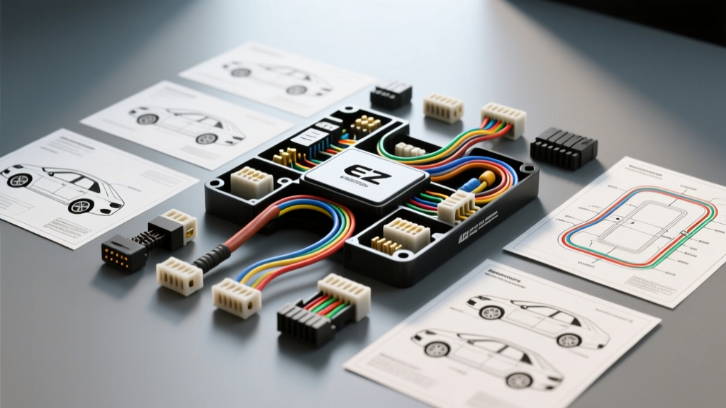
Introduction to EZ Wiring Harness Troubleshooting
Installing a universal harness, such as the popular EZ Wiring 14-circuit or 21-circuit hot rod kits, is a rite of passage for classic car builders. However, reading the basic EZ wiring harness instructions only gets the wires routed; it does not prepare you for the inevitable electrical gremlins that arise during first startup. Universal harnesses rely on the builder to correctly mate bulkhead connectors, establish proper ground planes, and match specific AWG wire gauges to high-draw components. When the key turns and nothing happens—or worse, when a fusible link melts—randomly probing with a test light is a recipe for damaged ECUs and melted insulation. This guide provides a systematic, step-by-step troubleshooting flow tailored specifically to EZ Wiring universal kits, ensuring you can diagnose and rectify faults using professional automotive electrical standards.
Pre-Flight Checklist: Before You Turn the Key
Before engaging the starter, you must verify the foundational architecture of the harness. According to SAE J1128 standards for low-tension primary cable, wire gauge and insulation type are critical for safety and voltage delivery.
- Main Battery Feed: Verify that the main power feed from the battery to the starter solenoid and the alternator is a minimum of 4 AWG (or 1/0 AWG for high-compression engines). The EZ Wiring main fuse block feed should be tapped into this with a minimum 8 AWG wire protected by a 100A-150A MAXI fuse or fusible link.
- Engine Block Ground: A universal harness is only as good as its return path. Ensure a 2 AWG braided ground strap connects the engine block directly to the chassis or battery negative terminal.
- Firewall Bulkhead: Inspect the EZ Wiring rubber grommet and bulkhead connector. Ensure no pins are pushed back ("backed out") in the plastic housing, which is a common cause of intermittent circuit failure.
The Step-by-Step Troubleshooting Decision Tree
Follow this diagnostic flow based on your primary symptom. Do not skip steps; electrical faults cascade through universal harnesses.
Symptom 1: Complete Electrical Blackout (No Dash, No Crank, No Lights)
If the vehicle exhibits zero electrical life, the fault lies in the main power distribution before the fuse block.
- Check the Main Fusible Link / MAXI Fuse: Locate the primary protection device near the battery. Use a multimeter in continuity mode. If blown, do not simply replace it; you have a dead short to ground on the main 8 AWG red feed wire.
- Verify Fuse Block "BAT" Terminal: EZ Wiring fuse blocks have a dedicated main power stud. Ensure the heavy red wire is secured with a proper ring terminal and star washer, torqued to 15-20 in-lbs. A loose connection here causes high resistance and voltage starvation.
- Test the Ignition Switch Feed: Trace the heavy red wire from the fuse block to the ignition switch "BAT" terminal. Probe the terminal with the switch OFF. You should read full battery voltage (12.4V - 12.6V). If 0V, the break is between the fuse block and the switch.
Symptom 2: Engine Cranks but No Spark (Ignition Circuit Fault)
This is the most common issue when adapting modern harnesses to classic V8s, particularly when swapping between points, HEI, and MSD systems.
- Trace the Pink Ignition Wire: The EZ Wiring kit uses a 12 AWG Pink wire for switched 12V ignition. Probe this wire at the fuse block with the key in the "RUN" position. You must see 12.2V or higher.
- Diagnose HEI Distributor Wiring: If running a GM HEI distributor, the Pink wire must route directly to the "BAT" terminal on the HEI cap. A common mistake is wiring it to the "TACH" terminal, which will result in zero spark and a fried module.
- Check for Ballast Resistor Interference: Universal harnesses often include a resistance wire or ballast resistor for classic points-style coils. If you upgraded to an HEI or MSD 6AL box, you must bypass or remove this resistor. Full 12V is mandatory for electronic ignition; a voltage drop below 10V at the coil will cause the module to shut down under load.
Symptom 3: Headlights Flicker or Fail on High Beam
Headlight circuits draw massive amperage. Relying on the factory floor dimmer switch without relays often overloads the EZ Wiring harness.
- Verify Dimmer Switch Inputs/Outputs: The harness feeds the dimmer switch via a 12 AWG Red wire (Low Beam) and 12 AWG Light Blue wire (High Beam). Probe the output side of the dimmer while clicking between high and low. If voltage drops below 11V at the switch, the internal contacts are failing or the upstream wire is undersized.
- Implement a Headlight Relay Upgrade: For halogen or LED conversions, the EZ Wiring headlight circuit should only trigger relays. Run dedicated 10 AWG power feeds directly from the fuse block to 30A SPDT relays, using the harness headlight wires purely as low-amp trigger signals.
- Inspect Radiator Support Grounds: Headlights ground through the body. Scrape away all paint and primer at the grounding points on the radiator support. Use a star washer and apply dielectric grease to prevent corrosion.
EZ Wiring Color Code & Circuit Reference Chart
Keep this reference table handy when tracing circuits through the engine bay and under-dash routing. Note that while EZ Wiring follows standard GM color codes, always verify with your specific kit's schematic.
| Circuit Function | Wire Color | AWG Size | Fuse Rating | Destination / Notes |
|---|---|---|---|---|
| Main Ignition (Switched) | Pink | 12 AWG | 15A | HEI BAT, MSD, Carb Solenoid |
| Starter Solenoid Signal | Purple | 10 AWG | 20A | Solenoid "S" Terminal (Ford/GM) |
| Tail / Parking Lights | Brown | 14 AWG | 15A | Rear Harness, License Plate |
| Alternator Exciter | Yellow / White | 18 AWG | N/A (Inline 1A) | GM 10SI/12SI Terminal #1 |
| Turn Signal (Left Front) | Dark Blue | 14 AWG | 15A | Column Connector / Front Bucket |
| Turn Signal (Right Front) | Light Green | 14 AWG | 15A | Column Connector / Front Bucket |
Advanced Diagnostics: Voltage Drop Testing
When a component receives power but operates weakly (e.g., slow wipers, dim dash lights), a multimeter continuity test will not reveal the fault. You must perform a voltage drop test under load. As outlined by MAD Enterprises hot rod wiring guidelines, resistance creates heat and robs components of amperage.
- Set your multimeter to DC Volts.
- Turn the circuit ON (e.g., turn on the wipers or headlights).
- Place the Red probe on the battery positive terminal.
- Place the Black probe on the power feed terminal at the component (e.g., the wiper motor power stud).
- Interpret the Reading: A reading of 0.0V to 0.2V is acceptable. If you read 0.5V or higher, you have excessive resistance in the wire, a corroded bulkhead pin, or an undersized gauge. For ground-side testing, reverse the probes (Black to battery negative, Red to component housing).
Common Pitfalls and How to Avoid Them
- Over-Crimping Terminals: Using a cheap, non-ratcheting crimper on 12 AWG or 10 AWG wires often deforms the barrel, cutting copper strands. Always use a ratcheting terminal crimper calibrated for the specific AWG to ensure a gas-tight connection.
- Solder-Only Connections in High Vibration Zones: While soldering is great for bench electronics, soldering a wire directly to a starter solenoid or alternator post without a mechanical crimp will lead to fatigue failure. Solder is brittle; engine harmonics will snap the wire at the solder joint. Always crimp first, solder second, and seal with adhesive-lined heat shrink.
- Alternator 1-Wire vs. 3-Wire Confusion: EZ Wiring kits provide an exciter wire for 3-wire alternators (like the GM 10SI). If you install a modern 1-Wire (self-exciting) alternator, you must cap off the Yellow/White exciter wire. Leaving it exposed or grounding it will backfeed voltage into the fuse block, keeping the ignition circuit live even when the key is off.
Conclusion
Successfully navigating your EZ wiring harness instructions requires moving beyond simple plug-and-play assumptions. By treating the harness as a network of distinct circuits and applying systematic voltage drop testing, color-code tracing, and proper AWG verification, you transform a frustrating wiring nightmare into a reliable, show-quality electrical system. Always consult the official EZ Wiring technical documentation for kit-specific fuse block layouts and bulkhead pinouts before making permanent modifications.