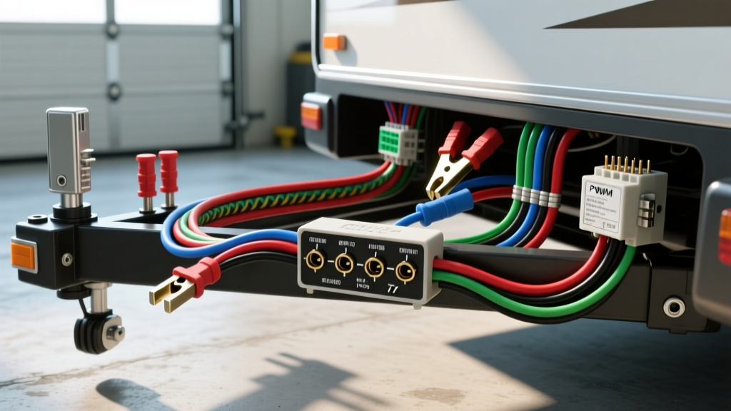
The Paradigm Shift in Tow Vehicle Architectures
Installing a wiring harness for a trailer on modern light-duty trucks and SUVs is no longer a simple matter of splicing into analog taillight circuits. Post-2015 vehicles heavily utilize Controller Area Network (CAN-bus) and Local Interconnect Network (LIN) protocols to manage exterior lighting. Furthermore, manufacturers employ Pulse Width Modulation (PWM) to monitor bulb resistance and detect outages. Directly tapping into these multiplexed circuits to feed a trailer harness will inevitably trigger hyper-flashing, CAN-bus fault codes, and potential Body Control Module (BCM) damage due to the added inductive load of trailer incandescent bulbs.
An advanced installation requires a fundamental understanding of signal isolation, voltage drop mitigation over extended harness runs, and strict adherence to RV Industry Association (RVIA) ANSI/RVIA LV standards for 7-way RV blade configurations. This guide details the engineering principles and practical execution required to integrate a heavy-duty 7-way trailer harness into a modern, PWM-controlled tow vehicle.
7-Way RV Blade Pinout and Load Specifications
The 7-way RV blade connector remains the industry standard for heavy towing, providing dedicated circuits for electric brakes and 12V auxiliary power. When fabricating or extending the vehicle-side harness, wire gauge selection must account for the total round-trip distance (vehicle to axle and back to the ground) and the specific amperage draw of the trailer. According to SAE J1128 standards for low-tension primary cable, cross-linked polyethylene (XLPE) insulation is mandatory for high-temperature resistance under the chassis.
| Pin | Function | RVIA Standard Color | Minimum AWG (30ft Run) | Max Continuous Load |
|---|---|---|---|---|
| 1 | Chassis Ground | White | 10 AWG (or 8 AWG) | 40A |
| 2 | Electric Brakes | Blue | 10 AWG | 20A (per axle) |
| 3 | Tail / Running Lights | Brown | 16 AWG | 10A |
| 4 | 12V Auxiliary Power | Black | 10 AWG | 30A |
| 5 | Right Turn / Stop | Green | 16 AWG | 10A |
| 6 | Left Turn / Stop | Yellow | 16 AWG | 10A |
| 7 | Reverse / Aux | Purple (or Red) | 16 AWG | 10A |
Note: While the RVIA color code is standard for the trailer side, OEM truck tow packages often utilize proprietary color palettes on the vehicle side of the 7-way pigtail. Always verify pinout continuity with a digital multimeter rather than relying on wire color matching.
Step-by-Step Heavy-Duty Harness Integration
1. Bypassing PWM with Isolated Relay Modules
To safely extract turn and stop signals from a PWM-controlled BCM without drawing current through the vehicle's sensitive logic circuits, you must install a powered, solid-state isolation module. These modules (often referenced in Tekonsha Technical Resources as powered converters) utilize high-impedance sense wires that detect the PWM voltage threshold without loading the circuit.
- Signal Interception: Use T-taps sparingly; instead, strip back the OEM loom and solder the module's sense wires (typically red for stop, yellow/green for turn) to the BCM output wires using a parallel connection.
- Powering the Module: Route a dedicated 12 AWG power feed directly from the vehicle battery positive terminal, protected by an inline 15A ATO blade fuse located within 18 inches of the battery.
- Load Output: The module's output side will provide a clean, steady 12V DC analog signal to the 7-way connector's turn/stop pins, completely isolating the trailer's incandescent or LED load from the truck's CAN-bus network.
2. Voltage Drop Mitigation for Electric Brake Circuits
Electric trailer brakes require precise voltage modulation from the in-cab brake controller. A voltage drop in the harness will result in delayed brake engagement and asymmetric braking force. The formula for voltage drop in a DC circuit is: VD = (2 × L × I × ρ) / A, where L is length, I is current, ρ is copper resistivity, and A is cross-sectional area.
For a 30-foot trailer pulling 15 amps across dual axles, a standard 12 AWG blue wire will yield a voltage drop of approximately 1.52V. This means a 12V command from the controller results in only 10.48V reaching the brake magnets. By upgrading the blue electric brake wire and the white ground wire to 10 AWG, the voltage drop is reduced to 0.95V, ensuring the brake controller's diagnostics read accurate amperage and the magnets engage with full proportional force.
3. Chassis Grounding and Terminal Torque Specifications
The most common point of failure in trailer harness installations is an inadequate chassis ground. The white 10 AWG ground wire must not be terminated to painted sheet metal or thin-gauge body panels. It must be anchored to the vehicle's main frame rail.
- Surface Preparation: Use a rotary wire brush to remove all paint, powder coat, and surface rust down to bare, bright steel over a 1-inch diameter area.
- Terminal Crimping: Utilize a ratcheting crimp tool (such as the Hozan P-707 or equivalent) to compress a heavy-duty, tinned-copper ring terminal onto the 10 AWG wire. Seal the crimp barrel with 3:1 adhesive-lined polyolefin heat shrink to prevent capillary moisture ingress.
- Hardware and Torque: Secure the ring terminal to the frame using an M8 or 5/16-inch Grade 8 bolt, a hardened flat washer, and an external-tooth star washer positioned directly against the bare metal. Torque the fastener to 18-22 lb-ft.
- Environmental Sealing: Coat the entire grounding junction with a dielectric corrosion inhibitor such as Nyogel 760G or a heavy application of fluid film to displace oxygen and prevent galvanic corrosion.
Advanced Troubleshooting: Ground Loops and Alternator Whine
When installing a wiring harness for a trailer that includes an auxiliary 12V charging circuit (Pin 4, Black Wire), technicians frequently encounter ground loops. If the trailer's interior 12V lighting or audio system shares a common ground with the vehicle's chassis through the 7-way plug, differences in ground potential between the truck frame and trailer frame can cause alternator whine in trailer-mounted speakers or flickering in LED marker lights.
The Fix: Implement a star-grounding topology on the trailer side. All high-current grounds (brakes, breakaway battery) should be tied to a heavy-duty bus bar bolted to the trailer tongue, while low-current signal grounds (interior LEDs, audio) are isolated or filtered. Additionally, verify that the 12V auxiliary circuit on the vehicle side is routed through a 30A continuous-duty solenoid relay, triggered by the ignition run circuit, to prevent the trailer from draining the tow vehicle's starting battery when parked.
Summary of Best Practices
Executing a professional-grade 7-way harness installation demands respect for modern vehicle network architectures and strict adherence to electrical physics. By utilizing PWM-isolated modules, upsizing high-draw circuits to 10 AWG, and executing flawless, environmentally sealed chassis grounds, you ensure reliable, fault-free towing operation regardless of the trailer's payload or electrical complexity.