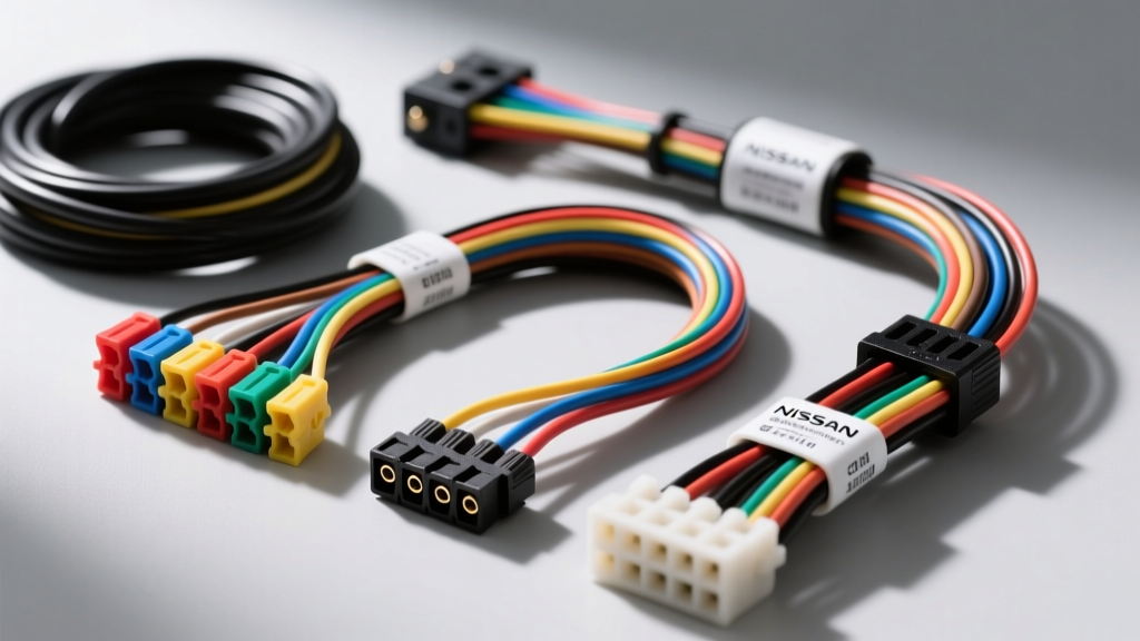
The Hidden Dangers of Generic Nissan Stereo Wiring Guides
Upgrading the head unit in a Nissan vehicle—whether it is an Altima, Rogue, Sentra, or Frontier—requires a precise understanding of the factory electrical architecture. When searching for a reliable color codes wiring harness nissan stereo wiring diagram, many DIYers and novice installers fall into the trap of relying on generic, universally applied color charts. This approach is not only inefficient; it is a primary catalyst for catastrophic electrical failures, blown Body Control Modules (BCMs), and persistent CAN-bus fault codes.
Nissan’s electrical systems, particularly from the 2007 model year onward, transitioned heavily into multiplex communication networks. The factory radio is no longer just an entertainment hub; it is a node on the vehicle's Controller Area Network (CAN-bus). Misinterpreting wire color codes or blindly splicing into a harness based on an outdated forum diagram can result in severe safety hazards and thousands of dollars in module replacement costs. This guide outlines the most critical mistakes, safety warnings, and technical specifications you must know before cutting into a Nissan factory harness.
The Myth of Universal Wire Colors: Nissan 40-Pin Connector Traps
One of the most pervasive errors in aftermarket car audio is assuming that wire colors remain consistent across different trim levels and model years. While the aftermarket standard (e.g., yellow for constant 12V, red for switched 12V, black for ground) applies to the aftermarket adapter harness, the factory Nissan harness operates under its own strict, and often confusing, color palette. Furthermore, Nissan frequently uses the same 40-pin connector shell for both base audio systems and premium Bose amplified systems, but the pin assignments differ drastically.
Below is a reference table for a standard non-Bose Nissan 40-pin connector (common in 2013-2018 Altima/Rogue platforms) highlighting where generic diagrams often lead installers astray.
| Pin Number | Factory Wire Color | Function | Common Diagram Mistake / Trap |
|---|---|---|---|
| 25 | Yellow | Battery Constant (12V+) | Confusing with switched 12V on older 20-pin Nissan harnesses. |
| 26 | Blue/Red or Green | Ignition Switched (12V+) | Assuming Red is switched. Nissan rarely uses solid Red for ignition. |
| 31 | Black | Chassis Ground | Grounding to the metal radio bracket instead of this dedicated pin. |
| 34 | Green | CAN-H (Data High) | Tapping this for an aftermarket amp turn-on signal (Causes U1000 codes). |
| 35 | Blue | CAN-L (Data Low) | Splicing into data lines, destroying 120-ohm impedance termination. |
| 17 | White/Red | Amp Turn-On (Bose Only) | Applying 12V to this pin on a non-Bose harness, shorting the BCM. |
| 3 | White | Front Left Speaker (+) | Misidentifying polarity; Nissan uses White/Black for negative (-). |
Mistake 1: The Bose Amplifier Bypass Blunder
If your Nissan is equipped with a factory Bose audio system, the head unit outputs a low-level, pre-amplified signal to a factory amplifier located under the passenger seat or in the rear cargo area. A common mistake found in poorly vetted wiring diagrams is the suggestion to simply 'splice' the aftermarket high-level speaker outputs into the factory Bose speaker wires. This results in severe audio distortion, clipping, and potential damage to the aftermarket head unit's internal amplifier ICs due to impedance mismatches.
The Correct Approach: You must use a dedicated Bose bypass harness (such as the Axxess XSVI-1217-NAV or similar PAC interfaces). These harnesses route the aftermarket head unit's low-level RCA signals directly to the factory amplifier's input pins, completely bypassing the factory head unit's pre-amp stage. Furthermore, the Bose system requires a specific data-driven turn-on signal. Applying a standard 12V remote turn-on wire to the factory Bose amp trigger pin will instantly fry the amplifier's logic board.
Mistake 2: Splicing CAN-Bus Data Lines for Accessories
Modern Nissans utilize the CAN-bus (Pins 34 and 35 on the 40-pin connector) to send data regarding steering wheel controls, vehicle speed, and backup camera triggers. A dangerous trend in amateur install guides is advising users to 'tap' into the CAN-H or CAN-L wires to derive a switched 12V signal or to trick the radio into turning on.
Safety Warning: The CAN-bus operates on a highly sensitive 2.5V to 3.5V differential signal. Piercing the insulation of these 20 AWG data wires with a T-tap or Scotchlok connector introduces capacitance and alters the twisted-pair impedance. This will trigger a U1000 CAN Communication Circuit fault code, which can cascade through the BCM and disable critical vehicle systems, including the intelligent key fob recognition and anti-theft immobilizer. Always use a dedicated data interface module (like an iDatalink Maestro or Axxess ASWC-1) that reads the CAN-bus optically or via high-impedance parallel sniffing without physically compromising the wire.
Mistake 3: Improper Grounding and Alternator Whine
Many generic diagrams suggest grounding the aftermarket radio's black wire to the nearest metal bolt in the dashboard crossmember. In modern unibody vehicles, the dashboard sub-frame is often coated in anti-corrosion dielectric paint or isolated by rubber bushings to reduce NVH (Noise, Vibration, and Harshness). Grounding to the chassis bracket creates a high-resistance ground, leading to voltage drops, head unit rebooting at high volumes, and severe alternator whine.
The Fix: Always terminate the radio ground wire directly to the factory harness ground pin (Pin 31) using the adapter harness. If you are running a new 14 AWG ground wire for an external amplifier, you must sand the paint down to bare, shiny metal, use a star washer to bite into the steel, and apply dielectric grease over the terminal to prevent galvanic corrosion. According to SAE J1128 standards for low-tension primary cable, ensuring proper gauge sizing and termination is critical to preventing thermal events.
Critical Safety Warnings for Nissan Harness Modifications
Beyond audio quality and module preservation, working inside the dashboard of a Nissan presents severe physical safety risks if proper protocols are ignored.
- Airbag Clock Spring and Squib Proximity: The steering column harness contains the airbag squib wires, which are universally jacketed in bright yellow per NHTSA and global automotive safety standards. When routing new harnesses or zip-tying adapter looms behind the radio stack, never apply pressure to or splice into yellow-jacketed wires. A stray 12V test probe or a short circuit against these lines can deploy the steering wheel airbag, causing severe injury and $1,500+ in replacement costs.
- Memory vs. Accessory Wire Swapping: Swapping the constant 12V (Yellow) and switched 12V (Red) wires is a classic error. While the radio will turn on, the constant memory circuit will now be tied to the ignition relay. This means every time you turn off the car, the radio loses its memory, but worse, the head unit remains in a 'standby' state drawing parasitic current from the battery whenever the key is removed, leading to a dead battery within 48 hours.
- Backup Camera 6V Voltage Regulator: On many Nissan models (e.g., 2016+ Rogue, Pathfinder), the factory backup camera does not operate on standard 12V. The factory head unit or a dedicated inline module steps the voltage down to 6V. Splicing an aftermarket camera's 12V reverse trigger directly into the factory camera power wire will instantly destroy the factory camera's CMOS sensor.
Proper Wire Termination Standards
The environment behind a Nissan dashboard is hostile, with temperature swings from below freezing to over 140°F (60°C) in direct summer sunlight. Twist-and-tape methods or standard electrical tape will inevitably fail, leading to short circuits against the metal HVAC housing.
For all 18 AWG speaker wires and 14 AWG power wires, the only acceptable termination method is the Mechanical Crimp and Solder technique, followed by adhesive-lined marine-grade heat shrink. The adhesive lining melts and seals the wire strands, preventing moisture ingress and copper oxidation. For detailed vehicle-specific fitment and verified harness pinouts, always cross-reference your specific VIN with established databases like the Crutchfield Vehicle Wiring Guide or the official Nissan Factory Service Manual (FSM) before making any irreversible cuts.
By respecting the complexity of the Nissan CAN-bus architecture, utilizing proper bypass interfaces, and adhering to strict termination standards, you can ensure a safe, reliable, and high-fidelity stereo upgrade without compromising the vehicle's core electrical systems.