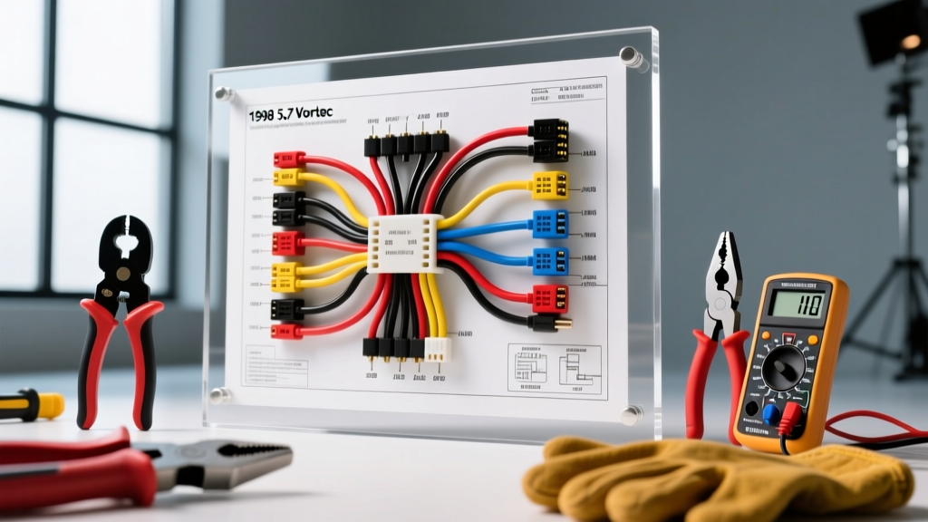
The 1998 5.7L Vortec Harness: Failure Points and Diagram Utility
The 1998 Chevrolet and GMC 5.7L Vortec (L31) engine is a benchmark of GMT400 reliability, but its electrical system has a well-documented Achilles heel. The 1998 model year utilizes the original Central Sequential Fuel Injection (CSFI) "spider" assembly. Over time, the poppet valves and fuel pressure regulator diaphragm leak raw fuel directly into the lower intake manifold. This fuel pools around the injector wiring pigtails, degrading the PVC insulation, wicking into the copper strands via capillary action, and ultimately corroding the EV1-style connector terminals. When mechanics and DIYers pull up a 1998 5.7 Vortec wiring harness diagram, they are usually chasing a P0200-series injector code or a PCM communication failure caused by this exact degradation.
Understanding the diagram is only the first step. The real challenge lies in executing a cost-effective, factory-grade repair. Replacing the entire engine harness is rarely necessary if you possess the correct schematic, specialized crimping tools, and an understanding of Delphi Packard connection systems. This analysis breaks down the exact costs, tooling requirements, and wire specifications needed to rebuild or repair the L31 harness correctly.
Cost Analysis: OEM vs. Aftermarket vs. Targeted Rebuild
When the harness insulation becomes brittle or the spider injector wires short out, owners face three distinct financial paths. Consulting the factory wiring diagram allows you to isolate the damaged circuits, often saving hundreds of dollars compared to a blind full-harness replacement.
| Repair Strategy | Estimated Cost | Pros & Cons |
|---|---|---|
| OEM Dealer Replacement | $850 - $1,300 | Pros: Plug-and-play, factory loom. Cons: Prohibitively expensive, uses the same outdated PVC insulation that will fail again. |
| Aftermarket Swap Harness | $450 - $700 | Pros: Modern insulation, great for LS swaps. Cons: Often lacks OEM routing clips, requires modifying firewall bulkheads for stock GMT400 applications. |
| Targeted Surgical Rebuild | $90 - $160 | Pros: Highly cost-effective, utilizes modern XLPE (cross-linked) wire and sealed connectors. Cons: Requires specialized crimping tools and schematic literacy. |
| Junkyard Pull | $150 - $250 | Pros: Cheap upfront. Cons: High risk of inheriting the exact same fuel-damaged, brittle harness. A financial trap. |
Why Junkyard Harnesses Are a Financial Trap
A 1998 L31 harness pulled from a salvage yard has been subjected to 25 years of under-hood thermal cycling and likely the same spider fuel leaks. The PVC insulation will snap when bent, and the internal copper oxidation is often invisible until you apply a load. Investing in a $40 ratcheting crimper and a $60 pigtail repair kit is vastly superior to gambling on a used harness.
Mandatory Tool Requirements for L31 Harness Fabrication
You cannot properly repair a GM wiring harness using standard stamped-terminal crimpers found in general hardware stores. The 1998 Vortec uses Aptiv (formerly Delphi Packard) Metri-Pack and Weather-Pack series connectors. These terminals feature specific insulation and wire crimp wings that require precise, ratcheting dies to achieve a gas-tight connection and proper pull-out retention.
- Ratcheting Terminal Crimper (Metri-Pack 150/280): You need a crimper calibrated for 0.35mm² to 2.0mm² (20 AWG to 14 AWG) open-barrel terminals. The Delphi 12094429 or an equivalent high-grade ratcheting tool is mandatory. A poor crimp here will cause a voltage drop, leading to a lean condition or a misfire on that specific cylinder.
- Weather-Pack Crimper: Required for the heated oxygen sensor (HO2S) circuits and main bulkhead connectors. These handle larger gauge wires (12 AWG to 10 AWG) and require a deeper, wider die.
- Precision Wire Strippers: Automatic wire strippers calibrated for 10-22 AWG. Nicking the copper strands on an 18 AWG injector control wire reduces its current-carrying capacity and creates a localized hot spot.
- Dual-Wall Adhesive Heat Shrink: Standard electrical tape is unacceptable in the intake valley. You must use 3:1 shrink ratio, adhesive-lined polyolefin heat shrink. When heated, the inner meltable adhesive seals the wire strands against fuel vapor and moisture ingress, mimicking the factory molded boots.
- Terminal Extraction Tools: A set of micro-picks and flat-blade extractors is required to release the locking tangs inside the 104-pin PCM connectors without snapping the plastic retention fingers.
Wire Gauge, AWG Ratings, and Color Code Reference
When referencing the 1998 5.7 Vortec wiring harness diagram, matching the correct AWG size and insulation type is critical for PCM longevity and sensor accuracy. According to SAE J1128 standards for low-tension primary automotive cable, modern repairs should utilize Cross-Linked Polyethylene (XLPE) wire, which offers superior resistance to heat, oil, and fuel compared to the OEM PVC.
| Circuit Function | OEM Wire Color | AWG Size | Connector / Terminal Type |
|---|---|---|---|
| Injector 1 Control (Cyl 1) | Dark Green | 18 AWG | Metri-Pack 280 / EV1 Pigtail |
| Injector 4 Control (Cyl 4) | Light Blue | 18 AWG | Metri-Pack 280 / EV1 Pigtail |
| PCM Ignition Feed (Battery) | Pink | 12 AWG | Metri-Pack 280 (Red PCM Conn) |
| Main PCM Ground | Black | 12 AWG | Ring Terminal / Metri-Pack 280 |
| MAF Sensor Signal | Yellow (Shielded) | 20 AWG | Metri-Pack 150 |
| Fuel Pump Relay Feed | Gray | 14 AWG | Metri-Pack 280 |
| VSS (Vehicle Speed Sensor) | Purple / Yellow | 20 AWG (Twisted Pair) | Weather-Pack |
Leveraging the Diagram for PCM 104-Pin Diagnostics
The 1998 GMT400 5.7L utilizes a 104-pin PCM, split across three distinct connectors: Black (C1), Blue (C2), and Red (C3). The wiring harness diagram is your roadmap for isolating whether a fault lies in the harness, the sensor, or the PCM driver itself.
Diagnostic Decision Tree: Injector Circuit Failure
If your scan tool indicates a P0204 (Injector Circuit/Open - Cylinder 4), do not immediately replace the spider assembly. Use the diagram and a digital multimeter (DMM) to perform a voltage drop test.
- Locate the Circuit: The diagram shows Cyl 4 injector control is a Light Blue wire originating from the Blue PCM Connector (C2), Pin B12.
- Check the EV1 Pigtail: Back-probe the EV1 connector at the spider assembly. With the key ON, engine OFF, you should see battery voltage (12V) on the Pink/White feed wire. If missing, trace the Pink wire back to the under-hood fuse block.
- Verify PCM Ground Path: Set your DMM to resistance (Ohms). Measure from the Light Blue wire at the injector pigtail to Pin B12 at the Blue PCM connector. It should read less than 0.5 Ohms. If it reads OL (Open Loop), the wire is broken internally—often due to fuel wicking and copper corrosion.
- Inspect the Harness Loom: Follow the harness where it passes behind the alternator bracket and dips into the intake valley. This is the primary flex point where insulation cracks and grounds out against the engine block, frying the PCM injector driver.
Conclusion: Invest in Tools, Not Replacement Harnesses
The 1998 5.7 Vortec wiring harness diagram reveals a logical, highly serviceable electrical architecture. The failures are almost entirely environmental, driven by the CSFI spider fuel leaks and under-hood heat. By investing $100 in proper Aptiv ratcheting crimpers, adhesive-lined heat shrink, and a spool of 18 AWG XLPE wire, you can surgically rebuild the damaged injector and sensor pigtails for a fraction of the cost of a dealer replacement. Always verify your pinouts against a factory Helm Incorporated GM Service Manual before applying power, as aftermarket repair manuals frequently transpose sensor ground and signal return circuits.