Introduction: The Economics of Marine Harness Repair
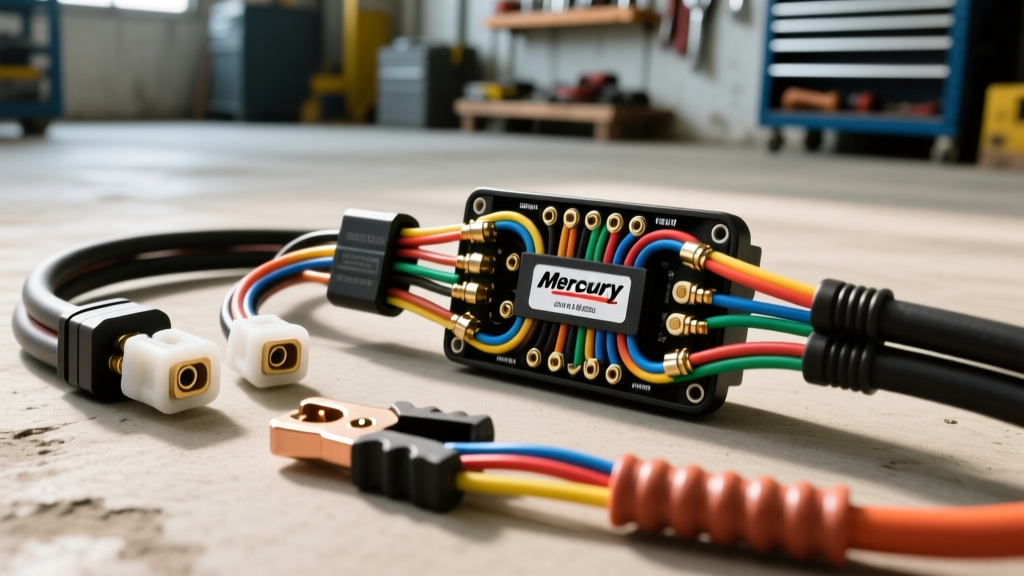
When diagnosing electrical gremlins on a Mercury outboard, the main engine wiring harness is often the primary suspect. Saltwater intrusion, UV degradation, and vibration-induced micro-fractures routinely compromise the integrity of the main 14-pin or 8-pin cannon plugs and the wires feeding them. While purchasing an OEM replacement harness is the path of least resistance, it is rarely the most economical. By leveraging a comprehensive Mercury outboard wiring harness diagram, marine technicians and advanced DIYers can fabricate custom replacement harnesses that exceed OEM specifications at a fraction of the cost.
This analysis breaks down the exact tooling requirements, material costs, and technical specifications needed to rebuild a Mercury main harness, ensuring compliance with ABYC (American Boat & Yacht Council) E-11 standards for DC electrical systems on boats.
Decoding the Mercury Outboard Wiring Harness Diagram
Before calculating costs, you must understand the schematic. Mercury has historically utilized a standardized color code for its ignition, starting, and accessory circuits. Interpreting the diagram correctly prevents catastrophic miswiring, particularly concerning the voltage regulator/rectifier and the starter solenoid.
Standard Mercury Main Harness Pinout & Wire Specifications
The following table outlines the standard 14-pin round connector configuration found on most Mercury V6 carbureted and early EFI outboards. Wire gauges are selected based on Ancor Marine's UL 1426 voltage drop charts for a standard 15-foot run from the helm to the transom.
| Pin | Function | Mercury Wire Color | AWG Size | Max Draw / Notes |
|---|---|---|---|---|
| A | Ignition (Switched 12V) | Purple | 14 AWG | Powers ECU/CDI and gauges |
| B | Choke / Primer | Dark Blue | 14 AWG | Activates choke solenoid |
| C | Starter Solenoid | Yellow/Red | 12 AWG | Requires minimal voltage drop |
| D | Battery Positive (Unswitched) | Red | 10 AWG | Memory keep-alive for EFI ECUs |
| E | Main Ground | Black | 10 AWG | Must terminate to clean engine block |
| F | Tachometer Signal | Gray | 16 AWG | Pulse signal from rectifier |
| G | Fuel Sender Signal | Pink | 16 AWG | Variable resistance to ground |
| H | Trim Sender Signal | Brown/White | 16 AWG | Analog resistance signal |
Tool Requirements for Marine-Grade Harness Fabrication
Automotive wiring tools are insufficient for marine environments. The primary cause of harness failure in outboards is capillary action—where moisture wicks down the inside of a wire strand due to improper crimping and sealing. To prevent this, your tooling must create a completely watertight, adhesive-lined termination.
Essential Tooling Investment Checklist
- Ratcheting Marine Crimper (Insulated Terminals): A ratcheting mechanism ensures the exact compression ratio required for marine-grade heat-shrink terminals. (Estimated Cost: $65 - $120)
- Adhesive-Lined Heat Shrink Tubing (3:1 Ratio): Polyolefin dual-wall tubing with an inner meltable adhesive layer. Standard automotive PVC shrink will crack and allow water ingress. (Estimated Cost: $35 for assorted kit)
- Temperature-Controlled Heat Gun: Required to evenly shrink the adhesive tubing without scorching the UL 1426 wire insulation. A reflector nozzle is highly recommended for 360-degree heating. (Estimated Cost: $80)
- Wire Strippers with AWG Stops: To prevent nicking the tinned copper strands, which reduces tensile strength and creates corrosion hotspots. (Estimated Cost: $30)
- Digital Multimeter (True RMS): For performing voltage drop tests across the newly fabricated harness. (Estimated Cost: $150+)
Total Initial Tool Investment: ~$360. While this seems steep, these tools are amortized over the lifetime of your marine electrical work and are mandatory for ABYC-compliant repairs.
Cost Breakdown: OEM Replacement vs. Custom Rebuild
Let us analyze the financial impact of replacing a degraded 14-pin main harness on a 150HP Mercury EFI outboard. OEM harnesses are often subject to marine dealer markups and backorder delays.
| Cost Factor | OEM Mercury Harness | Custom Fabricated Harness |
|---|---|---|
| Parts / Materials | $380.00 - $450.00 | $75.00 (Tinned wire, terminals, loom) |
| Connector Housing (14-Pin) | Included | $25.00 (Aftermarket sealed kit) |
| Labor / Time | 2 Hours (Routing & Plug-in) | 5 Hours (Stripping, crimping, sealing) |
| Corrosion Warranty | Standard 1-Year OEM | Lifetime (if adhesive shrink is used) |
| Total Estimated Cost | $405.00+ | $100.00 |
By utilizing the Mercury outboard wiring harness diagram to build your own harness, you save upwards of $300 per engine. Furthermore, custom harnesses allow you to upgrade the main battery feed and ground wires from the OEM 12 AWG to a more robust 10 AWG, significantly reducing voltage drop at the ECU during cranking.
Step-by-Step Fabrication & Diagnostic Savings
Step 1: Wire Selection and Routing
Never use Copper-Clad Aluminum (CCA) or bare copper automotive wire. You must purchase UL 1426 certified marine boat cable. This wire features individually tinned copper strands that resist galvanic corrosion. Measure the exact run from the helm key switch to the engine barrier block, adding 15% for service loops and drip loops at the transom bracket.
Step 2: Crimping and Adhesive Sealing
Strip the wire exactly to the terminal barrel depth. Insert the wire into the adhesive-lined terminal and use the ratcheting crimper. Once crimped, apply heat from the center of the barrel outward. You must visually confirm that the inner adhesive melts and squeezes out of both ends of the terminal barrel. This physical barrier is what prevents the 'green crust' of copper oxidation that plagues outboard harnesses.
Step 3: Voltage Drop Testing (The Ultimate Money Saver)
Many boaters mistakenly replace expensive starter motors or CDI boxes when the engine fails to crank or fire. According to marine diagnostic databases like ContinuousWave Marine Reference, over 60% of 'no-crank' scenarios on outboards are caused by voltage drop across the Yellow/Red starter wire or the Black ground wire.
Using your multimeter, set it to DC Volts. Place the positive probe on the battery post and the negative probe on the engine-side terminal of your new harness while an assistant turns the key to 'START'. A reading above 0.5V indicates a poor crimp or an undersized wire. Catching this during fabrication saves you from a $400 misdiagnosis on the water.
Conclusion: The Value of Diagram-Led Fabrication
Relying on a factory Mercury outboard wiring harness diagram transforms a daunting electrical failure into a highly manageable, cost-effective project. By investing in proper marine crimping tools and UL 1426 tinned wire, you not only bypass exorbitant OEM dealer costs but also engineer a harness that is physically superior to the one that left the factory floor. Whether you are repowering a classic V6 carbureted hull or troubleshooting an intermittent kill-switch ground on an Optimax, mastering the schematic and the crimp is the hallmark of true marine electrical proficiency.