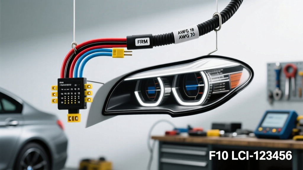
F10 LCI Headlight Electrical Architecture and Harness Reality
When diagnosing lighting faults on the F10 chassis Life Cycle Impulse (LCI) models, technicians frequently search for a comprehensive 2015 BMW 535i headlight wiring harness part number. However, BMW's electrical architecture for the F10 generation does not utilize a standalone, plug-and-play chassis-to-headlight harness that can be ordered as a single replacement assembly. Instead, the primary headlight wiring is integrated directly into the vehicle's main body and engine bay harness looms. Consequently, harness-related failures and part number searches almost exclusively pertain to the OEM repair pigtails, module adapter harnesses, and LED/Xenon ballast sub-harnesses that connect the Front Electronic Module (FEM) or Footwell Module (FRM3) to the headlight control units.
The 2015 BMW 535i LCI features either the Icon Adaptive LED headlights or the standard Adaptive Xenon HID setup. Both systems rely on a complex network of power, ground, and digital communication lines—specifically the Local Interconnect Network (LIN) bus and K-CAN—to manage stepper motors, LED drivers, and daytime running light (DRL) emitters. Understanding the specific repair harness part numbers, wire gauges, and pin configurations is critical for resolving 'Adaptive Headlight Malfunction' iDrive warnings without unnecessarily replacing entire headlight assemblies.
OEM 2015 BMW 535i Headlight Wiring Harness Part Numbers
Because the main harness is integrated, BMW provides specific repair cable kits (pigtails) designed to splice into the existing chassis wiring when the connector terminals suffer from micro-fretting corrosion, heat degradation, or capillary moisture wicking. Below are the primary OEM part numbers for the F10 LCI headlight sub-harnesses and repair kits.
| Component / Application | BMW Part Number | Connector Type | Wire Count |
|---|---|---|---|
| Adaptive LED Module Repair Pigtail (Left/Right) | 61 13 9 221 419 | 14-Pin MQS / SUMCO | 14 |
| Xenon HID Ballast Repair Cable (Pre-LCI/LCI Crossover) | 61 13 2 359 974 | 10-Pin AMP | 10 |
| LED Daytime Running Light (DRL) Emitter Adapter | 61 13 9 348 581 | 4-Pin Micro-Timer | 4 |
| Headlight Washer Nozzle Wiring Harness Repair | 61 12 9 231 842 | 2-Pin Waterproof | 2 |
Note: Always verify part numbers against the last 7 digits of your Vehicle Identification Number (VIN) via BMW ETK, as production month splits (e.g., March 2014 vs. November 2014) can dictate whether the vehicle uses an FRM3 or early FEM architecture.
F10 LCI 14-Pin Adaptive LED Pinout and Wire Gauge Specifications
The 14-pin connector is the primary interface for the Adaptive LED headlight module. The wiring utilizes BMW's standard color-coding nomenclature and specific cross-sectional areas to manage voltage drop over the distance from the FRM/FEM to the fender-mounted headlights. The connector utilizes TE Connectivity's Micro Quadlok System (MQS) terminals, which require specialized crimping tools for proper deformation.
| Pin | Function / Signal | Wire Color (BMW Code) | Cross-Section / AWG | Terminal Type |
|---|---|---|---|---|
| 1 | Terminal 30 (B+ Constant Power) | Red (RT) | 1.5mm² (16 AWG) | MQS Heavy Duty |
| 2 | Terminal 31 (Chassis Ground) | Brown (BR) | 1.5mm² (16 AWG) | MQS Heavy Duty |
| 3 | LIN Bus (Module Control) | White/Red (WS/RT) | 0.5mm² (20 AWG) | MQS Standard |
| 4 | K-CAN High | Red/White (RT/WS) | 0.5mm² (20 AWG) | MQS Standard |
| 5 | K-CAN Low | Brown/White (BR/WS) | 0.5mm² (20 AWG) | MQS Standard |
| 6 | Terminal 58G (Variable Illumination) | White/Blue (WS/BL) | 0.5mm² (20 AWG) | MQS Standard |
| 7 | Stepper Motor Phase A (Z-Height) | Yellow/Blue (GE/BL) | 0.75mm² (18 AWG) | MQS Standard |
| 8 | Stepper Motor Phase B (Z-Height) | Yellow/Red (GE/RT) | 0.75mm² (18 AWG) | MQS Standard |
| 9 | Stepper Motor Phase A (X-Swivel) | Green/Blue (GN/BL) | 0.75mm² (18 AWG) | MQS Standard |
| 10 | Stepper Motor Phase B (X-Swivel) | Green/Red (GN/RT) | 0.75mm² (18 AWG) | MQS Standard |
| 11 | Fan PWM Control (LED Cooling) | Blue/White (BL/WS) | 0.5mm² (20 AWG) | MQS Standard |
| 12 | Fan Tachometer Feedback | Blue/Yellow (BL/GE) | 0.5mm² (20 AWG) | MQS Standard |
| 13 | Headlight Washer Relay Trigger | Black/Yellow (SW/GE) | 0.75mm² (18 AWG) | MQS Standard |
| 14 | Shield / Drain Wire (CAN/LIN) | Bare / Shielded | N/A | Ground Strap |
Advanced Troubleshooting: Voltage Drop and LIN Bus Errors
The most common failure mode prompting a harness replacement on the 2015 535i is not a complete wire severance, but rather capillary wicking and LIN bus impedance faults. Moisture breaches the secondary weather seal of the 14-pin connector, leading to galvanic corrosion between the copper wire strands and the tin-plated MQS terminal. This increases resistance, causing the LED driver module to log internal voltage drop faults and shut down to protect the sensitive LED matrix.
Diagnostic Decision Tree for Adaptive Headlight Faults
- Symptom: iDrive displays 'Adaptive Headlights Inactive' + LED DRL flickering.
- Step 1 (Visual): Inspect the 14-pin connector at the base of the headlight housing. Look for green/white copper oxide buildup on Pin 1 (B+) and Pin 3 (LIN).
- Step 2 (Voltage Drop Test): With the headlights commanded ON via ISTA, measure the voltage drop across Pin 1 and Pin 2 at the harness side. A drop greater than 0.2V on the 1.5mm² power circuit indicates internal harness corrosion requiring pigtail replacement (Part 61139221419).
- Step 3 (Oscilloscope LIN Analysis): Back-probe Pin 3 (LIN Bus). According to the SAE J2602 LIN Bus Standard, a healthy BMW LIN bus should show a recessive state of ~11.5V-12.5V and a dominant state of ~1.0V-2.0V. If the dominant state rises above 3.5V, the harness has excessive resistance, or the FRM LIN driver is failing.
- Step 4 (Stepper Motor Binding): If the harness tests perfectly but the headlight fails Z-axis calibration, the issue is mechanical binding in the projector bowl, not the wiring.
Harness Replacement Protocol: Crimping vs. Soldering
When installing the OEM repair pigtail harness, do not solder the MQS terminals. The F10 headlight harness is routed through the fender liner and subjected to high-frequency vibration and extreme thermal cycling (proximity to the LED heat sinks and turbocharger ambient heat). Soldered joints create a rigid fulcrum point that leads to work-hardening and eventual copper fracture. Furthermore, soldering alters the characteristic impedance of the K-CAN and LIN bus twisted pairs, leading to signal reflection and communication timeouts.
Instead, utilize a TE Connectivity MATEnet or MQS specific ratcheting crimper (such as the TE Connectivity 58431-1 Crimp Tool). Strip the FLRY-A (Automotive PVC) or FLR2G (Automotive XLPE) wire precisely to 4.0mm. Ensure the wire brush of the crimp fully encapsulates the copper strands without cutting into the insulation support wings. After crimping, seal the splice using dual-wall polyolefin heat shrink tubing with an integrated meltable adhesive lining to prevent future capillary wicking.
FEM/FRM Coding and Stepper Motor Calibration
Replacing the headlight wiring harness or the LED control module itself is only half the repair procedure on the 2015 BMW 535i. The FRM (Footwell Module) stores the specific hardware index and calibration data for the Adaptive LED matrix. If a new module is installed alongside a new pigtail harness, the module must be coded to the vehicle.
- Connect a licensed ENET or ICOM interface and launch ISTA+ or E-Sys.
- Read the Vehicle Order (FA) and ensure the headlight option codes (e.g., S552A for Adaptive LED) are present.
- Code the FRM/FEM module to apply the correct FDL parameters for the LED driver.
- Execute the ABL (Test Plan) for Headlight Calibration. This routine commands the stepper motors (Pins 7-10) to sweep to their physical hard stops to establish a baseline zero-position for both the Z-axis (leveling) and X-axis (cornering swivel).
- Failure to perform this calibration will result in the headlights defaulting to a static, downward-angled 'safe mode', triggering a persistent dash warning despite the harness and modules being fully functional.
Authoritative References
- SAE International - J2602 LIN Bus Network Standard
- TE Connectivity - MQS Automotive Crimp Tooling Specifications
- BMW AG Technical Information System (TIS) - REP 63 12 500: Repairing Headlight Wiring Harness Connectors (F10/F18 LCI).