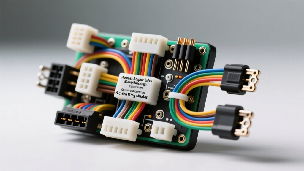
The Hidden Dangers of Aftermarket Harness Adapters
When performing an engine swap or integrating an aftermarket ECU, a high-quality harness adapter is the central nervous system of your build. However, the market is flooded with poorly engineered adapters that cut corners on wire gauge, shielding, and pinout accuracy. Relying on these subpar components does not just lead to frustrating diagnostic headaches; it introduces severe safety hazards, including electrical fires and sudden loss of vehicle control. According to the SAE J1128 standard for low-tension primary cables, automotive wiring must withstand extreme thermal and chemical environments. Many budget adapters fail this basic requirement.
This guide breaks down the five most critical mistakes made when installing or selecting a harness adapter, complete with actionable safety warnings and technical specifications to keep your build reliable and safe.
Mistake #1: Undersized Main Power and Ground Feeds
The most common and dangerous mistake in adapter harness fabrication is using undersized wire for high-amperage circuits. Many mass-produced LS swap adapters use 14 AWG wire for the main ECM power relays and fuel pump feeds to save on copper costs.
The Consequence: Voltage Drop and Thermal Runaway
A modern Gen III/IV LS ECM can draw up to 15 amps continuously, with transient spikes exceeding 25 amps during injector firing. Pushing 25 amps through a 14 AWG wire over a 10-foot run (20 feet total circuit length) results in a voltage drop of nearly 1.3 volts. This starves the ECU, causing erratic injector pulse widths and misfires. Worse, the wire insulation can melt, leading to a dead short and an engine bay fire.
The Fix: Follow AWG to Fuse Sizing Strictly
Always verify the wire gauge against the circuit maximum amperage and physical length. Use TXL or GXL cross-linked polyethylene (XLPE) insulated wire, which offers superior heat resistance compared to standard PVC.
Mistake #2: Improper CAN-Bus Termination and Routing
Modern vehicles rely on Controller Area Network (CAN) bus systems for critical communication between the ECM, TCM, and BCM. A harness adapter that bridges the OBD2 port to the ECU must correctly route and terminate these high-speed data lines.
Safety Warning: The 120-Ohm Rule
CAN-Bus networks require a 120-ohm termination resistor at each physical end of the bus to prevent signal reflection. If your adapter lacks these resistors, or if they are placed incorrectly, the network will experience data collisions. This manifests as a No Communication error on scan tools or a vehicle entering limp mode at highway speeds, which is a massive safety risk.
- OBD2 Pin 6 (CAN High): Typically Dark Green or White/Blue (0.5mm² / 20 AWG).
- OBD2 Pin 14 (CAN Low): Typically Light Blue or White/Green (0.5mm² / 20 AWG).
- Twist Rate: Wires must be twisted at a minimum of 2 twists per inch to reject electromagnetic interference (EMI).
Mistake #3: Splicing Inside Weather-Pack Cavities
When adapting an OEM harness to an aftermarket ECU, installers often cut off the factory connector and splice in new pigtails. Doing this inside the drip loop or too close to the connector cavity compromises the weather seal.
Capillary Action and Corrosion
If moisture breaches a poorly sealed splice, it will travel via capillary action through the copper strands directly into the ECU or sensor. Delphi Metri-Pack 2.8 and Weather-Pack connectors rely on specific wire insulation diameters to create a watertight seal with the silicone plug seals. Splicing alters this diameter, rendering the seal useless. Always crimp new terminals directly to the wire, or use adhesive-lined heat shrink (minimum 3:1 shrink ratio) at least 3 inches away from the connector body.
Harness Adapter Wire Gauge and Circuit Protection Chart
Use this reference chart when auditing your harness adapter for safety and compliance. Data aligns with standard automotive circuit protection guidelines and Holley EFI wiring specifications.
| Circuit Type | Max Continuous Amps | Minimum Wire Gauge (TXL/GXL) | Recommended Fuse / Breaker | Common Connector Type |
|---|---|---|---|---|
| Main ECM / ECU Relay Feed | 25A - 30A | 10 AWG | 30A Maxi Fuse | Metri-Pack 2.8 / Ring Terminal |
| Fuel Pump Primary Feed | 20A - 25A | 10 AWG (8 AWG for >15ft) | 30A Relay / 25A Fuse | Weather-Pack 4-Way |
| Ignition Coil Power (V8) | 15A | 12 AWG | 20A ATO Fuse | Metri-Pack 1.5 |
| O2 Sensor Heater Circuit | 8A - 12A | 14 AWG | 15A Mini Fuse | Delphi LS O2 Pigtail |
| Injector Bank (4 per side) | 12A | 14 AWG | 15A ATO Fuse | Multec 2 / USCAR |
| CAN-Bus / Sensor 5V Ref | < 1A | 20 AWG (Shielded) | ECM Internal Protection | Metri-Pack 1.5 |
Mistake #4: Grounding to Painted or Anodized Surfaces
An adapter harness is only as good as its ground returns. A frequent and catastrophic error is securing ECM ground rings to painted chassis brackets, powder-coated engine blocks, or anodized cylinder heads.
The Consequence: Floating Grounds and Fried Modules
Paint and anodizing are electrical insulators. If the main ECU ground relies on a painted surface, the return current will seek the path of least resistance, often back through low-voltage sensor grounds (like the TPS or MAF sensor). This floating ground pushes 12V+ through 5V reference circuits, instantly destroying the ECM internal drivers.
The Fix: Star Washers and Bare Metal
Always grind away paint, powder coat, and rust down to bare, shiny metal at every ground termination point. Use a stainless steel star washer between the ring terminal and the block to bite through minor surface oxidation. For LS swaps, the primary ECM grounds must be secured directly to the back of the cylinder heads using the factory M8x1.25 bolts torqued to 18 lb-ft.
Mistake #5: Ignoring Sensor Shielding and EMI Interference
High-output ignition systems and alternators generate massive Electromagnetic Interference (EMI). If your harness adapter uses standard unshielded wire for critical low-voltage sensors, the ECU will read false data.
Critical Shielded Circuits
- Crankshaft Position Sensor (CKP): Unshielded CKP wires will pick up noise from the ignition coils, causing the ECU to miscalculate engine timing or shut off fuel injection entirely.
- Wideband O2 Controllers: Analog signal wires from wideband controllers to the ECU must be shielded to prevent voltage spikes that falsely lean out the air/fuel ratio, risking detonation and melted pistons.
Safety Warning: When using shielded wire, the drain wire (the bare copper strand inside the shield) must be grounded only at the ECU end. Grounding both ends creates a ground loop, turning the shield into an antenna that amplifies EMI rather than blocking it.
Diagnostic Decision Tree for Adapter Failures
When troubleshooting a newly installed harness adapter, follow this logical sequence to isolate the fault safely:
- Symptom: ECU powers on, but injectors/coils do not fire.
- Check: Main relay ground and ignition switch 12V feed (Pink/White wire on GM).
- Fix: Verify continuity from the ignition switch pin to the ECM Pin 20. Ensure the relay coil ground is tied to a clean block ground, not a sensor ground.
- Symptom: OBD2 Scanner fails to link, but engine runs.
- Check: CAN-Bus wiring at OBD2 Pins 6 and 14. Measure resistance across pins with the battery disconnected.
- Fix: If resistance is not exactly 60 ohms (two 120-ohm resistors in parallel), check for missing termination resistors in the adapter harness.
- Symptom: Erratic TPS or MAF readings at idle.
- Check: 5V reference circuit and sensor ground wire gauge.
- Fix: Upgrade sensor ground wires to 16 AWG and ensure they share a dedicated, clean ground plane with the ECM, isolated from high-amp return paths.
Final Safety Directives
Never compromise on the integrity of your harness adapter. Use proper open-barrel crimpers for Metri-Pack terminals, seal all connections with the correct silicone plugs, and route wiring at least 4 inches away from exhaust manifolds and high-tension ignition coils. By respecting AWG limits, enforcing strict grounding protocols, and properly terminating data networks, you ensure your vehicle electrical system is both reliable and safe for the road. For further reading on primary cable specifications, refer to the SAE International standards database.