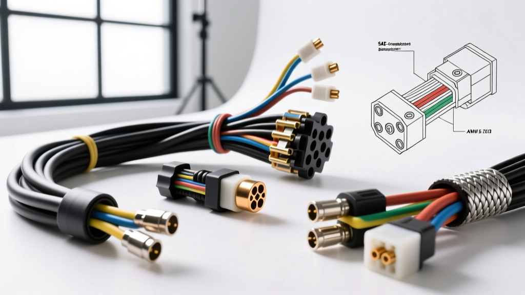
Introduction to Engine Wiring Harness Repair Standards
Executing a proper engine wiring harness repair requires far more than simply restoring electrical continuity. The modern engine bay is a hostile environment characterized by extreme thermal cycling, high-frequency vibration, and exposure to corrosive hydrocarbons. When performing an engine wiring harness repair, technicians and fabricators must adhere strictly to automotive-grade specifications to ensure the repaired circuit matches the mechanical and environmental resilience of the original OEM assembly. This technical reference outlines the core Society of Automotive Engineers (SAE) standards, terminal crimp matrices, and connector extraction protocols required for professional-grade harness restoration and custom fabrication.
Wire Insulation Specifications: TXL, GXL, and SXL
Before initiating any engine wiring harness repair, it is critical to select the correct primary wire type. Standard PVC-insulated wire is entirely unsuitable for engine bay applications due to its low melting point and poor chemical resistance. According to SAE J1128 standards, automotive primary cable must utilize Cross-Linked Polyethylene (XLPE) insulation. Understanding the differences between the three main XLPE variants is essential for routing and bundling:
- TXL (Thin-Wall Cross-Linked): Features the thinnest insulation wall (0.41mm for 18 AWG). It is the industry standard for modern OEM engine harnesses where space and weight are at a premium. Rated for continuous operation up to 125°C.
- GXL (General Cross-Linked): Offers a slightly thicker wall (0.58mm for 18 AWG) providing enhanced abrasion resistance for harness branches routed near sharp chassis brackets or exhaust heat shields.
- SXL (Standard Cross-Linked): The thickest variant (0.79mm for 18 AWG), typically reserved for heavy-duty commercial applications or high-wear zones where the harness is subjected to physical impact.
Terminal Crimp Matrix: AWG to Barrel Specifications
The foundation of any reliable engine wiring harness repair is the mechanical crimp. A correctly executed crimp forms a gas-tight cold weld between the terminal barrel and the copper wire strands, preventing oxygen and moisture from causing galvanic corrosion. The following matrix details the precise specifications for open-barrel (stamp-and-form) terminals commonly found in modern ECU and sensor connectors.
| Wire Gauge (AWG) | Wire Cross-Section (mm²) | Insulation Diameter (mm) | Terminal Barrel Size | Standard Crimp Height (mm) | Insulation Color Code |
|---|---|---|---|---|---|
| 20 AWG | 0.50 | 1.40 - 1.60 | 0.14 - 0.22 | 0.65 - 0.75 | Red |
| 18 AWG | 0.80 | 1.60 - 1.80 | 0.35 - 0.50 | 0.90 - 1.00 | Red |
| 16 AWG | 1.30 | 1.80 - 2.10 | 0.50 - 0.80 | 1.15 - 1.25 | Blue |
| 14 AWG | 2.00 | 2.10 - 2.40 | 0.80 - 1.25 | 1.45 - 1.55 | Blue |
| 12 AWG | 3.00 | 2.40 - 2.70 | 1.50 - 2.00 | 1.80 - 1.95 | Yellow |
The Physics of Crimp vs. Solder in High-Vibration Zones
A common misconception in amateur engine wiring harness repair is that soldering provides a superior connection. In high-vibration automotive environments, solder is a primary point of failure. When solder wicks under the wire insulation via capillary action, it creates a rigid boundary between the flexible wire and the stiff, solder-saturated section. Under engine vibration, this stress riser concentrates mechanical fatigue, inevitably leading to a fracture just outside the solder joint. Furthermore, residual flux from rosin-core solder can become conductive when exposed to engine bay humidity, causing parasitic draws or cross-circuit leakage. Professional harness builders strictly utilize precision ratcheting crimp tools to achieve the aforementioned cold-weld compression, completely eliminating the need for solder.
Connector Pin Extraction and Insertion Protocols
Repairing a damaged circuit often requires removing a single compromised terminal from a multi-pin connector housing. Forcing a terminal out without properly disengaging the primary and secondary locks will destroy the connector housing and the terminal retention tangs.
Aptiv (Delphi) Metri-Pack 280 and Weather-Pack Series
Aptiv connection systems dominate domestic and many import engine harnesses. It is vital to understand the mechanical difference between the two primary families:
- Weather-Pack (Pull-to-Seat): The terminal is crimped to the wire, and the assembly is pulled through the front of the connector housing. The silicone weather seal is crimped onto the wire insulation. Extraction requires inserting a specialized pick tool into the front of the cavity to depress the dual beryllium-copper locking tangs on the terminal while simultaneously pulling the wire from the rear.
- Metri-Pack 280 (Push-to-Seat): The terminal is inserted from the rear of the housing. The primary lock consists of a flexible plastic lance molded directly into the connector housing that snaps over a shoulder on the terminal. To extract, a thin-walled stainless steel extraction tube must be slid over the terminal from the rear to flatten the plastic lance, allowing the terminal to be pushed out the front.
TE Connectivity Deutsch DT Series
Commonly found in heavy-duty, diesel, and motorsport engine management harnesses, the Deutsch DT series utilizes a two-part retention system. The terminal features an internal primary barb that bites into the housing. However, the defining feature is the secondary Wedge Lock (DTM/DT wedge). Before attempting pin extraction, the orange, green, or black plastic wedge lock must be pried out from the front mating face using a small flathead pick. Only after the wedge lock is removed can the terminal locking tang be depressed from the rear for extraction. Detailed mechanical drawings for these retention mechanisms can be found in the TE Connectivity Deutsch DT technical documentation.
Environmental Sealing: Dual-Wall Polyolefin Specifications
When splicing wires during an engine wiring harness repair, the environmental seal is just as critical as the electrical connection. Standard PVC heat shrink is unacceptable as it shrinks unevenly and lacks an internal adhesive, allowing water ingress via capillary action along the wire strands.
Professional repairs mandate the use of Adhesive-Lined Dual-Wall Polyolefin Heat Shrink. The outer wall is made of radiation-cross-linked polyolefin, providing high abrasion resistance and a 3:1 or 4:1 shrink ratio. The inner wall is coated with a thermoplastic Ethylene Vinyl Acetate (EVA) adhesive.
| Parameter | Specification |
|---|---|
| Outer Wall Material | Cross-Linked Polyolefin |
| Inner Adhesive Material | Ethylene Vinyl Acetate (EVA) |
| Adhesive Melting Point | 85°C ± 5°C |
| Minimum Shrink Temperature | 120°C |
| Continuous Operating Temp | -40°C to +125°C |
| Dielectric Strength | > 20 kV/mm |
When applying heat, the technician must observe the EVA adhesive extruding slightly from both ends of the shrink tube. This visual indicator confirms that the adhesive has fully melted, flowed into the interstitial spaces between the copper strands, and created a waterproof, strain-relieved seal.
Post-Repair Validation: Voltage Drop Thresholds
The final step in any engine wiring harness repair is dynamic validation. A continuity test with a multimeter is insufficient, as it applies negligible load and cannot detect high-resistance faults caused by a poor crimp or corroded terminal. Technicians must perform a dynamic voltage drop test under loaded conditions.
Using a digital multimeter, measure the voltage across the repaired connection (from one end of the wire/terminal to the other) while the circuit is actively drawing current (e.g., testing an injector circuit during engine cranking or a cooling fan circuit while active). According to standard automotive electrical diagnostics:
- Standard Power Circuits: Maximum allowable voltage drop is 0.10V (100mV) per connection or splice.
- PCM Sensor Grounds and Low-Level Signal Circuits: Maximum allowable voltage drop is strictly 0.05V (50mV). Exceeding this threshold on a 5V reference circuit or a thermistor ground will cause the ECU to miscalculate sensor data, resulting in erratic fuel trims or phantom misfire codes.
By adhering to these stringent SAE specifications, utilizing the correct cross-linked insulation, and executing precision cold-weld crimps, technicians can ensure that an engine wiring harness repair will withstand the brutal realities of the engine bay for the lifetime of the vehicle.