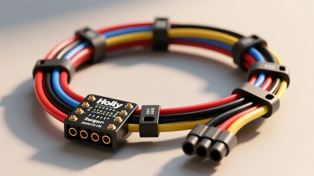
Holley Sniper EFI Wiring Harness Architecture
The transition from carburetion to electronic fuel injection requires a fundamental shift in how we approach automotive electrical systems. At the core of the Holley Sniper EFI wiring harness is a highly integrated, sealed architecture designed to withstand the harsh underhood environment of high-performance V8 engines. Unlike older, multi-layered aftermarket harnesses that require splicing dozens of individual circuits, the Sniper platform utilizes a centralized 34-pin ECU connector paired with dedicated sub-harnesses for injectors, sensors, and the wideband oxygen sensor.
Understanding the physical topology of this harness is critical for advanced installers. The main harness is wrapped in high-temperature split loom and utilizes TXL (cross-linked polyethylene) insulated wire, which complies with SAE J1128 standards for low-tension primary cable. This insulation provides superior resistance to heat, abrasion, and automotive fluids compared to standard PVC wire. When routing the main trunk through the firewall or along the chassis, maintain a minimum clearance of 4 inches from exhaust manifolds and moving linkages to prevent thermal degradation and mechanical chafing.
Main ECU Connector Pinout & Wire Gauge Specifications
The 34-pin sealed connector is the central nervous system of the Sniper ECU. Below is a detailed specification chart of the most critical circuits within the main harness. Note that wire gauges are strictly engineered to handle specific current loads while minimizing voltage drop over the standard harness length.
| Pin ID | Circuit Function | Wire Color | AWG Size | Technical Notes |
|---|---|---|---|---|
| A1 | Battery 12V+ (Constant) | Red | 10 AWG | Connects directly to battery + terminal. Do not route through ignition switch. |
| A2 | Main ECU Ground | Black | 10 AWG | Must terminate at a clean, bare metal point on the engine block or cylinder head. |
| C1 | Switched 12V (Ignition) | Pink | 18 AWG | Requires a clean 12V source active only in 'Run' and 'Start' positions. |
| B4 | TPS Signal Return | Light Blue | 20 AWG | High-impedance input. Susceptible to EMI; keep away from ignition coils. |
| B14 | Coolant Temp Sensor (CTS) | Dark Green | 20 AWG | Provides negative temperature coefficient (NTC) resistance signal to ECU. |
| D5 | Fuel Pump Relay Trigger | Blue | 18 AWG | Low-side driver. Switches ground to activate external fuel pump relay. |
Sensor Input Wiring & Shielding Requirements
The analog sensor inputs (TPS, CTS, IAT) operate on a 5-volt reference system generated internally by the Sniper ECU. The 5V reference wire (typically Orange or Red/White depending on the specific sub-harness revision) is a shared bus. Critical Warning: Never apply 12V to the 5V reference circuit or sensor signal wires. Doing so will instantly destroy the ECU's internal voltage regulator and analog-to-digital converters.
For the Throttle Position Sensor (TPS), the harness utilizes a 3-wire configuration: 5V Reference, Sensor Ground, and Signal Return. Because the TPS signal operates in the millivolt to 4.5V range, it is highly susceptible to Radio Frequency Interference (RFI). If you are running an MSD 6AL or similar capacitive discharge ignition box, route the TPS sub-harness at least 6 inches away from the ignition coil and spark plug wires. If erratic TPS readings persist, verify that the sensor ground wire shares the exact same ground node as the ECU main ground to prevent ground loop offsets.
Wideband O2 Sensor: Bosch LSU 4.9 Integration
The Sniper harness terminates in a specific 5-pin connector for the Bosch LSU 4.9 wideband oxygen sensor. This is not a standard narrowband O2 sensor; it utilizes a complex planar zirconia cell and an integrated heating element. The five wires include:
- Heater Ground (White): Pulse-width modulated by the ECU to control heater temperature.
- Heater +12V (Black): Supplied via a dedicated fused circuit.
- Pump Cell (Grey): Measures oxygen ion current.
- Reference Cell (Yellow): Provides the baseline atmospheric oxygen reference.
- Calibration Resistor (Red): Contains a factory-laser-trimmed resistor specific to the exact sensor.
Advanced Fabrication Rule: Never cut, shorten, or lengthen the wideband O2 sensor harness. The calibration resistor is housed inside the connector plug and is matched to the specific sensor's manufacturing tolerances. Altering the wire length changes the circuit resistance, which will result in permanently skewed Air/Fuel Ratio (AFR) readings. If the sensor must be relocated, extend the ECU-side harness, not the sensor-side pigtail.
Ignition Integration & Tach Signal Routing
Proper integration of the Sniper EFI harness with your ignition system is mandatory for sequential fuel injection and accurate RPM calculation. The White wire in the main harness is the Tach Input signal. The wiring methodology changes drastically based on your ignition architecture:
- Points / Standard HEI Distributors: The white wire connects directly to the negative terminal of the ignition coil or the dedicated 'TACH' output terminal on the HEI cap. The ECU expects a 12V square wave signal.
- MSD / Capacitive Discharge Ignitions: Do NOT connect the white wire to the negative coil terminal on an MSD system; the voltage spikes exceed 400V and will fry the ECU tach input. Instead, connect the white wire to the MSD box's dedicated 'Points' or 'Tach Output' terminal, or utilize the Holley MSD Magnetic Pickup Adapter (PN 558-300).
- Lockout Distributors / Crank Trigger: For sequential injection, the ECU requires both a crank and cam signal. The harness includes a shielded twisted-pair cable for the magnetic pickup. Ensure the shield drain wire is grounded only at the ECU end to prevent ground loops, as recommended by Bosch Motorsport Technical Guidelines.
Power Distribution: Relays, Fuses, and AWG Sizing
A common failure point in amateur EFI installations is overloading the ignition switch or the ECU's internal drivers. The Holley Sniper EFI wiring harness includes a 20A inline fuse on the main Battery 12V+ (Red) wire. However, high-demand peripherals like electric cooling fans, high-pressure fuel pumps (e.g., Walbro 450 or AEM 340), and electric water pumps must be isolated using external ISO mini relays.
For the fuel pump circuit, the Blue wire on the Sniper harness acts as a low-side driver (it provides a ground path when the fuel pump should be active). Wire this blue wire to Pin 85 of a standard 30A/40A ISO relay. Connect Pin 86 to a switched 12V source, Pin 30 directly to the battery via a 30A fuse using 10 AWG wire, and Pin 87 to the fuel pump positive terminal using 12 AWG wire. This ensures the high current draw of the fuel pump bypasses the ECU entirely, protecting the delicate internal circuitry.
Advanced Troubleshooting: Ground Loops & EMI Interference
When diagnosing electrical anomalies in a Sniper EFI installation, a digital multimeter (DMM) and an oscilloscope are mandatory tools. Below is a decision tree for common harness-related failure modes:
Symptom: Erratic TPS Voltage or 'System Voltage High' Error
- Root Cause: Ground loop offset or alternator AC ripple bleeding into the DC system due to poor engine grounding.
- Diagnostic Step: Set DMM to DC Volts. Measure voltage between the engine block and the negative battery terminal while cranking. It should read less than 0.05V. Next, measure between the cylinder head and the chassis firewall.
- Resolution: Install a minimum 4 AWG braided copper ground strap from the engine block to the chassis, and a 10 AWG strap from the cylinder head to the firewall. Clean all termination points down to bare, shiny metal using a wire brush and apply dielectric grease to prevent corrosion.
Symptom: Engine Stalls at Idle / AFR Reads Lean (16.0+)
- Root Cause: Wideband O2 sensor heater circuit voltage drop, causing the sensor to fall below operating temperature (750°C) and default to a false lean reading.
- Diagnostic Step: Back-probe the Heater +12V wire at the O2 sensor connector with the engine running. If voltage drops below 11.5V, the harness or fuse block has excessive resistance.
- Resolution: Upgrade the O2 heater power feed wire from 18 AWG to 14 AWG, and ensure it is sourced directly from the battery side of the main fuse block, not a shared accessory circuit.
By treating the Holley Sniper EFI wiring harness not just as a bundle of wires, but as a precision data and power delivery network, you ensure the longevity, reliability, and peak performance of your electronic fuel injection system. Always reference the official Holley Sniper EFI Technical Documentation for firmware-specific pinout revisions before making any custom harness modifications.