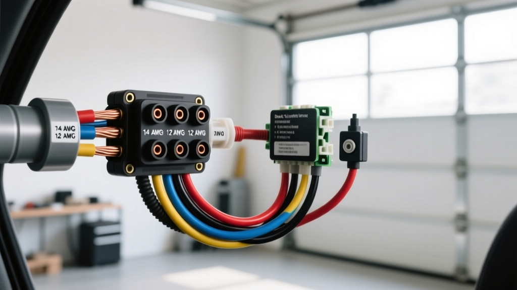
Introduction to Brake Controller Wiring Harness Standards
A properly engineered brake controller wiring harness is the critical bridge between a tow vehicle's electrical architecture and a trailer's electromechanical braking system. Whether you are fabricating a custom harness for an LS-swapped trail rig, installing an OEM-style pigtail on a late-model heavy-duty truck, or diagnosing a faulty 7-way RV blade connector, adhering to strict wire gauge (AWG) and pinout specifications is non-negotiable. Undersized wiring or incorrect pin assignments will result in severe voltage drop, delayed brake actuation, or catastrophic thermal failure at the connector.
This technical specification reference details the exact wire color codes, AWG requirements, circuit protection parameters, and pin configurations required for modern proportional and time-delayed brake controllers, referencing SAE International J286 and standard RVIA guidelines.
7-Way RV Blade Connector: Pinout and Wire Specifications
The 7-way RV blade connector is the industry standard for light and medium-duty towing. The brake controller relies primarily on the Electric Brakes pin (Blue) and the 12V Auxiliary pin (Black) to function, but the entire harness must be wired correctly to ensure the controller receives the necessary stoplight trigger and ground references.
| Pin Position | Function | Standard Wire Color | Min. AWG Size | Circuit Protection |
|---|---|---|---|---|
| Center | 12V Auxiliary Power | Black | 10 AWG | 30A Auto-Reset Breaker |
| 1 o'clock | Reverse / Aux | Purple | 12 AWG | 20A Fuse |
| 3 o'clock | Right Turn / Stop | Green | 12 AWG | 20A Fuse |
| 5 o'clock | Electric Brakes Output | Blue | 10 AWG | 30A / 40A Breaker |
| 7 o'clock | Chassis Ground | White | 10 AWG (or 8 AWG) | N/A (Direct to Chassis) |
| 9 o'clock | Left Turn / Stop | Yellow | 12 AWG | 20A Fuse |
| 11 o'clock | Tail / Marker Lights | Brown | 12 AWG | 20A Fuse |
Critical Harness Routing Notes
- Ground Circuit (White): The white ground wire must be terminated directly to the vehicle chassis or battery negative using a ring terminal and star washer. Never rely on the trailer hitch ball for the primary ground path; high resistance here will cause the brake controller to display an 'NC' (No Connection) error or pulse the brakes erratically.
- Brake Output (Blue): This circuit carries the PWM (Pulse Width Modulation) signal from the controller to the trailer magnets. It must be routed away from high-voltage ignition wires and alternator outputs to prevent electromagnetic interference (EMI), which can cause the controller's internal accelerometer to miscalculate deceleration rates.
Brake Controller Pigtail Harness Specifications
Most aftermarket and OEM-integrated brake controllers (such as the Tekonsha Prodigy P3 or Redarc Tow-Pro Elite) utilize a 4-pin or 6-pin pigtail harness that plugs directly into the back of the controller module. When fabricating a replacement pigtail or hardwiring a universal unit, use SAE J1128 GXL (cross-linked thin-wall) wire for its superior 125°C thermal rating and abrasion resistance.
| Pigtail Wire Color | Function | AWG Requirement | Connection Point |
|---|---|---|---|
| White | System Ground | 10 AWG | Vehicle Chassis / Battery (-) |
| Black | 12V Power Input | 10 AWG | Battery (+) via 30A Breaker |
| Blue | Brake Output to Trailer | 10 AWG | 7-Way Pin 5 (Electric Brakes) |
| Red | Stoplight Switch Trigger | 18 AWG | Brake Pedal Switch (Cold Side) |
Note on 6-Pin Pigtails: Heavy-duty applications often use a 6-pin harness that adds an Orange wire (illumination/dash dimmer) and a Yellow wire (manual override or secondary output). Always verify the specific manufacturer's pinout diagram before applying 12V power, as applying battery voltage to the 18 AWG Red trigger wire will instantly destroy the controller's internal logic board.
Circuit Protection and Relay Integration
Automotive electrical systems experience severe voltage spikes and inrush currents. Trailer brake magnets are highly inductive loads. When the controller ceases the PWM signal, the collapsing magnetic field generates a flyback voltage spike that can damage the controller's MOSFETs if not properly managed.
- Auto-Reset Breakers: The Black (12V) and Blue (Output) 10 AWG circuits must be protected by 30A Type 1 (auto-reset) circuit breakers mounted within 18 inches of the battery positive terminal. Do not use standard blade fuses for the main brake output circuit, as the cyclic nature of PWM can cause thermal fatigue and nuisance blowing in standard fuses.
- Heavy-Duty Upgrades: For triple-axle trailers (6 brake magnets drawing up to 18-22 amps continuous), upgrade the Blue output wire to 8 AWG and install a 40A auto-reset breaker to prevent voltage drop and thermal throttling of the harness.
Voltage Drop Calculation Reference
Voltage drop is the silent killer of trailer braking performance. A brake magnet requires a minimum of 10.5V to achieve full clamping force. If the harness wire is too thin, or the run is too long, the magnets will underperform, leading to extended stopping distances.
Voltage Drop Formula
VD = (2 x K x I x L) / CM
- VD: Voltage Drop
- K: Specific resistance of copper (12.9 ohms per mil-foot at 75°C)
- I: Current in Amps (e.g., 12A per axle)
- L: One-way length of wire in feet
- CM: Circular Mils of the wire (10 AWG = 10,380 CM; 8 AWG = 16,510 CM)
| Wire Gauge | Run Length (One Way) | Current Draw (Dual Axle) | Calculated Voltage Drop |
|---|---|---|---|
| 10 AWG | 15 Feet | 24 Amps | 1.09V (Acceptable) |
| 10 AWG | 25 Feet | 24 Amps | 1.82V (Marginal) |
| 8 AWG | 25 Feet | 24 Amps | 1.14V (Optimal) |
For any tow vehicle exceeding 20 feet in length (e.g., extended wheelbase crew cabs), routing 8 AWG SGT wire for the Blue brake output circuit is highly recommended by etrailer technical engineering guidelines to ensure optimal brake response.
Troubleshooting Harness Faults: Symptom-Cause-Fix
When diagnosing a brake controller wiring harness, follow this structured decision tree to isolate the fault efficiently.
Symptom 1: Controller Displays 'NC' (No Connection) with Trailer Plugged In
- Check 7-Way Pin 5 (Blue): Use a multimeter to test for continuity between the vehicle's 7-way Blue pin and the controller's Blue pigtail wire. An open circuit indicates a broken wire or a pushed-out terminal inside the 7-way housing.
- Check Trailer Ground: An 'NC' code often means the controller's 12V probe signal cannot find a return path through the trailer's white ground wire. Clean the trailer tongue ground point to bare metal.
- Inspect Connector Pins: Spread the female terminals inside the trailer plug using a dental pick. Loose terminal tension will prevent the probe signal from registering.
Symptom 2: Brakes Lock Up Immediately Upon Plugging In
- Verify Pinout Crossover: This is almost always caused by a miswired 7-way adapter. If the 12V Auxiliary (Black, Center Pin) is crossed with the Electric Brakes (Blue, 5 o'clock), full battery voltage is sent directly to the magnets the moment the harness is plugged in.
- Test with Circuit Tester: Use a high-impedance digital multimeter to verify the center pin reads 12.6V and the 5 o'clock pin reads 0V (or a pulsed mV signal from the controller) with the ignition on and brakes off.
Symptom 3: Controller Powers On, But No Output to Brakes
- Verify Red Trigger Wire: The controller needs to know the vehicle is decelerating or the brake pedal is pressed. Probe the Red 18 AWG wire at the controller plug. It should read 0V at rest, and 12V when the brake pedal is depressed. If it reads 12V at all times, it is connected to the wrong side of the stoplight switch or a constant 12V source.
- Check 30A Main Breaker: If the internal breaker has tripped and failed to reset (or if a cheap fuse was used and blew), the controller may have enough residual logic power from the stoplight circuit to turn on the screen, but lacks the amperage from the Black 10 AWG wire to drive the brake magnets.
Terminal Crimping and Weatherproofing
A harness is only as reliable as its terminations. For all 10 AWG and 12 AWG connections in a brake controller wiring harness, abandon standard vinyl-insulated crimps. Use nylon-insulated heat-shrink butt connectors with a ratcheting crimper. The internal thermoplastic adhesive lining melts during the heat-shrink process, creating a waterproof, dielectric seal that prevents copper oxidation and green corrosion (verdigris) inside the barrel. Apply a silicone-based dielectric grease to all 7-way blade pins to prevent galvanic corrosion between the brass vehicle pins and the aluminum or copper trailer contacts.
For further reading on commercial and heavy-duty towing harness variations, consult the RVIA Technical Resources database and SAE J560 standards for 7-way round pin commercial configurations.