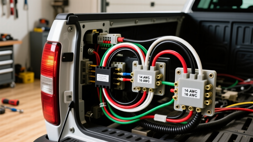
Understanding the CHMSL Circuit Architecture
Wiring a Center High Mount Stop Lamp (CHMSL) on a truck cap requires more than simply splicing into the nearest brake light wire. Modern truck lighting systems utilize multiplexed networks, pulse-width modulation (PWM), and body control modules (BCM) that monitor circuit resistance. Tapping directly into a taillight circuit without a proper truck cap wiring harness for third brake light can trigger BCM faults, cause hyper-flashing, or result in the cap light illuminating when the turn signals are activated.
This complete wiring diagram walkthrough breaks down the two primary methods for routing a CHMSL harness: utilizing the factory OEM upfitter cap plug (common on late-model Ford, GM, and Toyota trucks) and executing a clean T-harness tap on older or base-model trucks lacking a dedicated cap plug.
Diagram Walkthrough: OEM Upfitter Plug vs. Taillight Tap
Before cutting wire or stripping connectors, you must identify your truck’s specific rear lighting architecture. The routing diagram changes drastically depending on whether your truck is equipped with a factory tow/cap prep package.
Path A: The OEM Cap Plug (Ford F-150 / GM Silverado Architecture)
Most modern half-ton and heavy-duty trucks with a factory tow package include a blunt-cut pigtail or a sealed connector zip-tied near the rear bumper or tucked behind the driver-side taillight assembly. This is the OEM upfitter plug.
- Ford F-150 (2015-Present): Look for a 4-pin or 6-pin blunt-cut pigtail behind the driver-side rear wheel well. The dedicated CHMSL wire is typically Light Blue with a White tracer (LT BLU/WHT) or Orange/Light Green (ORG/LT GRN) depending on the exact model year.
- GM Silverado/Sierra (2019-Present): The upfitter harness is often located above the spare tire. The dedicated CHMSL circuit wire is Light Blue (LT BLU).
- Toyota Tacoma/Tundra: Often features a dedicated white 4-pin or 5-pin connector plugged into a dummy socket near the rear crossmember.
Diagram Flow: OEM CHMSL Wire (14 AWG) → Upfitter Pigtail → 4-Way Flat / 7-Way RV Adapter → Truck Cap 7-Way Receptacle → Cap CHMSL LED Array.
Because this circuit is already isolated and fused at the BCM (usually a 15A mini-fuse in the under-hood BJB), no additional relays or inline fuses are required for standard LED cap lights drawing under 2 Amps.
Path B: T-Harness Taillight Tap (Universal / Base Model Trucks)
If your truck lacks an OEM upfitter plug, you must extract the CHMSL signal from the existing rear lighting harness. Do not splice into the combined stop/turn signal wires. If you do, your cap's third brake light will flash with the turn signals. You must tap the dedicated high-mount brake light wire running along the driver-side frame rail.
- Locate the CHMSL Feed: Trace the harness from the cab's rear CHMSL down the driver-side frame rail. Use a digital multimeter (DMM) to probe the wires while a helper presses the brake pedal (without the turn signal engaged). The correct wire will show 12V+ only when the brake pedal is depressed.
- Install a PWM Filter / Relay (If Required): If your truck uses PWM for bulb-out detection (common in RAM and newer GM trucks), tapping directly will cause the cap light to strobe. You must wire a standard 12V 30A automotive relay or a dedicated PWM-to-12V converter module.
- T-Harness Integration: Use a sealed, injection-molded T-harness connector rather than vampire taps (which compromise the wire jacket and invite corrosion).
Wire Gauge, Fuse, and Connector Specifications
Adhering to SAE J1128 standards for low-tension primary cable is critical for under-vehicle routing where heat, moisture, and road debris are constant threats.
| Component | Specification | Purpose / Notes |
|---|---|---|
| Main Harness Wire | 14 AWG GXL or SXL | Cross-linked polyethylene insulation handles 125°C+ near exhaust routing. |
| Cap Drop Wire | 16 AWG GPT | Standard primary wire; sufficient for LED arrays drawing < 5A. |
| Inline Fuse | 5A to 10A ATO/ATC | Required only on Path B (T-Harness Tap). Protects the tap point from a dead short in the cap. |
| Connectors | Deutsch DT or Weather-Pack | Sealed silicone seals prevent capillary action water ingress into the copper strands. |
| Ground Point | M6 Ring Terminal to Frame | Must be sanded to bare metal and coated with dielectric grease. |
Step-by-Step Routing and Grounding Protocol
A wiring diagram is only as reliable as its physical execution. Follow these routing steps to ensure long-term reliability of your truck cap wiring harness for third brake light circuits.
1. Routing Through the Bed to Cap
Never route the harness over the top of the bed rails where the cap sits; the clamping pressure will eventually crush the wire jacket and cause a short. Instead, route the harness through the front bulkhead of the bed (using an existing rubber grommet or drilling a new hole and installing a nylon firewall grommet). Use split-loom tubing and UV-resistant zip ties to secure the harness along the inside of the cap's roof ribs.
2. Establishing a True Ground
According to Delphi Automotive's electrical troubleshooting guides, over 70% of automotive lighting failures are ground-related. Do not rely on the cap's aluminum frame or the truck bed as a ground path. Run a dedicated 14 AWG ground wire from the CHMSL assembly directly to a clean, unpainted steel point on the truck frame or the cap's dedicated grounding bolt, applying anti-oxidation compound to the terminal.
Troubleshooting the CHMSL Harness
Even with a perfect diagram walkthrough, real-world variables can introduce faults. Use this diagnostic tree if your third brake light malfunctions after installation.
- Symptom: Light strobes or pulses rapidly.
Cause: PWM bulb-out detection from the BCM.
Fix: Install a 10,000µF capacitor across the 12V and Ground lines at the light, or use a dedicated PWM filter relay. - Symptom: Light illuminates with turn signals or running lights.
Cause: Tapped into the wrong circuit (combined stop/turn or tail circuit).
Fix: Move the tap to the dedicated CHMSL feed wire or use the OEM upfitter plug. - Symptom: Light is dim or flickers when the engine is off.
Cause: High resistance ground or undersized wire gauge causing voltage drop.
Fix: Perform a voltage drop test across the ground circuit. If reading >0.1V, clean the ground terminal or upgrade to 12 AWG wire.
Final Integration and Testing
Once the physical routing and connections are complete, perform a full lighting sequence test. Have a helper cycle the headlights, turn signals, hazard flashers, and brake pedal while you monitor the cap's CHMSL. For comprehensive pinout data and model-specific wire color codes, always cross-reference your vehicle's factory service manual or resources like MotorAllData before applying heat shrink and electrical tape. A properly executed truck cap wiring harness for third brake light will operate invisibly and reliably for the life of the vehicle.