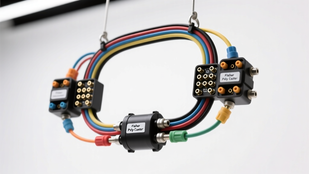
Fisher Poly-Caster Electrical Architecture Overview
The Fisher Poly-Caster power unit is the electro-hydraulic heart of many Minute Mount 2 and SEHP (Snowplow Electro-Hydraulic Power) snowplow systems. Unlike engine-driven PTO setups, the Poly-Caster relies entirely on the vehicle's electrical system to drive the hydraulic pump and actuate the directional solenoid valves. Because commercial snow removal operates in highly corrosive, high-vibration, and sub-zero environments, the Fisher Poly-Caster wiring harness must adhere to strict SAE J1128 primary cable standards to prevent voltage drop, insulation embrittlement, and catastrophic short circuits.
This complete wiring diagram walkthrough dissects the high-current motor circuits, the low-current valve solenoid pinouts, and the multiplex control module integration. Whether you are troubleshooting a sluggish angle cylinder or fabricating a custom replacement harness, understanding these specific AWG ratings, wire color codes, and connector types is mandatory for reliable plow operation.
Primary Power and Motor Ground Circuit (High-Current Path)
The hydraulic pump motor on a Poly-Caster unit typically draws between 120A and 180A under peak load (such as when lifting the plow or breaking over a heavy snowbank). This necessitates a robust high-current path that bypasses standard vehicle fusing in favor of heavy-duty fusible links or MEGA fuses.
Battery Feed and Motor Solenoid
- Wire Gauge: 6 AWG (or 4 AWG for extended runs exceeding 10 feet to mitigate voltage drop).
- Wire Color: Solid Black (Battery to Solenoid), Solid Black (Solenoid to Motor).
- Fusing: 150A or 200A MEGA fuse located within 18 inches of the battery positive terminal.
- Connector Type: Heavy-duty ring terminals (3/8-inch stud) with adhesive-lined heat shrink sealing.
The motor is engaged via a heavy-duty continuous or intermittent duty solenoid (often a Trombetta or White-Rodgers style relay). The control circuit that triggers this solenoid uses a 10 AWG Black wire with an Orange tracer. When the control module grounds this trigger wire, the solenoid closes, sending full battery voltage to the Poly-Caster motor.
Motor Ground Path
A common failure point in the Fisher Poly-Caster wiring harness is the motor ground. The motor case itself is often used as a ground path, or a dedicated 6 AWG Black ground wire is routed from the motor housing to the vehicle chassis. Never rely solely on the mounting bolts for the ground path. Always use a dedicated grounding lug bonded to a clean, bare-metal surface on the chassis, treated with dielectric grease to prevent galvanic corrosion from road salt.
Poly-Caster Valve Solenoid Pinout and Wiring Table
The directional control of the plow (Raise, Lower, Angle Left, Angle Right) is managed by hydraulic cartridge valves actuated by electromagnetic solenoids. In classic SEHP Poly-Caster harnesses, these are direct 12V DC coils. In newer FleetFlex multiplex systems, the control module uses Pulse Width Modulation (PWM) to feather the spool shift, reducing the amperage spike and hydraulic shock.
Below is the standard wiring specification chart for the Poly-Caster valve block harness:
| Valve Function | Wire Color | AWG Size | Connector Pin | Typical Resistance |
|---|---|---|---|---|
| Raise (Lift) | Red w/ White Tracer | 14 AWG | Pin 4 | 4.0Ω - 5.0Ω |
| Lower (Drop) | Black w/ White Tracer | 14 AWG | Pin 5 | 4.0Ω - 5.0Ω |
| Angle Left | Green w/ White Tracer | 14 AWG | Pin 6 | 4.0Ω - 5.0Ω |
| Angle Right | Brown w/ White Tracer | 14 AWG | Pin 7 | 4.0Ω - 5.0Ω |
| Solenoid Ground | Solid Black | 12 AWG | Pin 8 (Common) | < 0.5Ω to Chassis |
Note: Always verify resistance with a digital multimeter (DMM) at the harness connector, not directly at the coil, to include the harness wiring in your diagnostic reading. A reading of 'OL' (Open Loop) indicates a broken wire or failed internal coil winding.
Multiplex Control Module Integration (3-Plug System)
Modern Fisher Poly-Caster setups utilize the 3-Plug Multiplex system to communicate between the in-cab joystick/controller and the plow-mounted control module. The harness is divided into three distinct circuits:
- Plug 1 (Power): 2-pin heavy-duty connector carrying the main 12V+ feed and the heavy chassis ground.
- Plug 2 (Lighting): 11-pin Metri-Pack or Weather-Pack style connector routing headlamps, turn signals, and parking lights from the plow grid to the truck's lighting module.
- Plug 3 (Control/Data): 4-pin or 6-pin connector carrying the multiplex data bus (CAN-bus or proprietary PWM) and the 12V ignition-switched wake-up signal.
According to the official Fisher Engineering Mechanics Guides, the data pins on Plug 3 are highly sensitive to voltage fluctuations and moisture ingress. If the dielectric grease is omitted during reconnection, capillary action will draw saltwater into the terminal crimps, causing data packet loss. This manifests as intermittent joystick response or the control module defaulting to 'safe mode' (disabling all hydraulics).
Diagnostic Walkthrough: Voltage Drop and Continuity Testing
When a Poly-Caster motor cranks slowly or a valve solenoid clicks but fails to shift the spool, the issue is rarely the component itself; it is almost always a voltage drop across the wiring harness. Follow this SAE J343 compliant testing procedure:
Step 1: The Motor Solenoid Voltage Drop Test
- Set your DMM to DC Volts.
- Connect the red probe to the battery positive terminal and the black probe to the motor-side terminal of the main solenoid.
- Activate the plow lift function (draws maximum amperage).
- Read the voltage. A healthy harness and solenoid will show a voltage drop of 0.2V or less. A reading of 0.5V or higher indicates corroded terminals, undersized wire, or failing internal solenoid contacts.
Step 2: Valve Solenoid Trigger Verification
- Back-probe the control module connector using a T-pin or specialized back-probe tool.
- Set the DMM to DC Volts.
- Command an 'Angle Left' from the cab.
- Verify that 12V (or a 12V PWM duty cycle) is present at the Green/White wire pin. If voltage is present at the module but the valve doesn't click, the fault lies in the harness continuity between the module and the valve block.
Common Failure Modes and Harness Repair Protocols
Repairing a Fisher Poly-Caster wiring harness requires more than just twisting wires together and applying electrical tape. The environment demands automotive-grade repair protocols:
- Terminal Fretting Corrosion: Vibration causes micro-movements between the male and female terminals in the 3-plug connectors, wearing away the tin plating and creating high resistance. Fix: Replace both male and female terminals using a proper crimping die (not pliers), and pack the connector cavity with Nyogel 760G or equivalent dielectric grease.
- Insulation Chafing: The harness routing near the A-frame and lift cylinder is prone to rubbing against the steel pivot points. Fix: Wrap the harness in split loom tubing, followed by high-quality harness tape (Tesa 51036), and secure it with UV-resistant zip ties away from moving hydraulic lines.
- Solenoid Coil Burnout: Caused by leaving the ignition on with the plow attached, or a stuck relay keeping the coil energized. Fix: Always install an inline 10A mini-fuse on the solenoid trigger feed if not already present, and verify the control module's auto-shutoff timeout feature is active.
By adhering to these wiring specifications and diagnostic procedures, you ensure that the Fisher Poly-Caster system operates with the speed and reliability required for commercial snow and ice management.