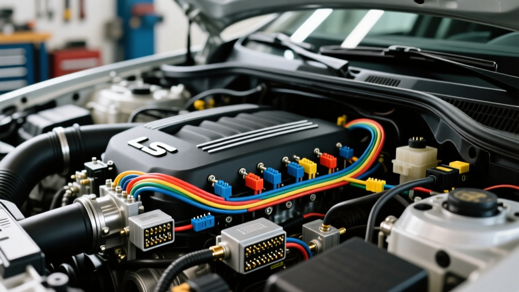
Introduction: Why Replace the OEM LS Engine Wiring Harness?
When performing an engine swap or restoring a high-mileage vehicle, deciding to replace engine wiring harness assemblies is often the difference between a reliable build and a perpetual electrical gremlin hunt. The OEM Gen III and Gen IV GM LS V8 engine harnesses (found in 5.3L LM7, 5.7L LS1, and 6.0L LQ4 applications) were originally manufactured using TXL (Thin Cross-Link) insulated wire. While TXL wire meets the SAE J1128 standard for under-hood temperature resistance, 20 years of heat cycling, oil exposure, and vibration causes the insulation to become brittle. Cracking insulation near the exhaust manifolds and rear oxygen sensors leads to short circuits, misfires, and PCM (Powertrain Control Module) damage.
This complete wiring diagram walkthrough will guide you through the architecture of a replacement LS engine harness, decoding the critical PCM pinouts, injector adapter kits, sensor circuits, and grounding strategies required for a bulletproof installation.
Phase 1: Decoding the PCM Connector Pinouts (C1 and C2)
The brain of the LS V8 is the PCM, typically utilizing two 80-pin Delphi connectors (C1 and C2) on 1997-2006 models. The C1 connector is generally green and handles the powertrain outputs (injectors, coils, transmission solenoids), while the C2 connector is blue and manages sensor inputs and main power distribution. When you replace engine wiring harness components, verifying these pinouts is mandatory before applying 12V power.
| Connector | Pin | Circuit Name | Wire Color | AWG | Function / Notes |
|---|---|---|---|---|---|
| C1 (Green) | 20 | INJ 1 (Cyl 1) | Dark Green | 18 | Injector Control (Low Side Driver) |
| C1 (Green) | 19 | INJ 8 (Cyl 8) | Yellow/Black | 18 | Injector Control (Low Side Driver) |
| C1 (Green) | 3 | IC 1 (Coil 1) | White | 18 | Ignition Coil Trigger Signal |
| C2 (Blue) | 1 | Battery Power | Red | 12 | Constant 12V (PCM Memory/KAM) |
| C2 (Blue) | 24 | Ignition | Pink | 14 | Switched 12V (Run/Crank) |
| C2 (Blue) | 16 | MAF Signal | Yellow | 20 | Mass Air Flow Frequency Input |
Notice that the PCM controls the injectors and coils via the ground side (low-side drivers). The power side of the injectors and coils is fed by a common Pink 14 AWG wire that receives 12V only when the ignition relay is energized. If your replacement harness uses a fused relay setup, ensure the relay feed wire is rated for at least 30A to handle the combined amperage of eight 5.3L injectors and eight ignition coils simultaneously.
Phase 2: Injector and Ignition Coil Mapping
A major hurdle when you replace engine wiring harness setups for LS swaps is the injector connector discrepancy. Early Gen III engines (1997-2004) utilize Bosch EV1 (Jetronic) square connectors, while later Gen IV engines (2005+) use EV6 (USCAR) slim connectors. If you are dropping an LM7 into a classic muscle car but using modern truck injectors, you will need an EV1-to-EV6 adapter harness kit. These adapters must use 18 AWG TXL wire to maintain flexibility and prevent voltage drop across the adapter joint.
For the ignition coils, the LS1/LS6 uses a taller, round 4-pin connector, whereas the LS2/LS3/Truck coils use a shorter, rectangular 4-pin connector. The pinout for the truck coil connector is critical:
- Pin A (Left): Ground (Black) - 18 AWG
- Pin B (Middle Left): PCM Trigger (White/Violet/etc.) - 18 AWG
- Pin C (Middle Right): Not Used (Empty on most truck coils)
- Pin D (Right): Switched 12V Power (Pink) - 14 AWG
Misrouting the Pink 12V wire to the PCM trigger pin will instantly fry the internal driver inside the PCM, a catastrophic failure mode commonly seen in DIY harness replacements.
Phase 3: Critical Sensor Circuits and Wire Colors
Sensor circuits demand shielded or twisted-pair wiring to prevent Electromagnetic Interference (EMI) from the high-voltage ignition coils and alternator. According to official GM Service Manuals published by Helm Inc., the Mass Air Flow (MAF) sensor and Intake Air Temperature (IAT) sensor share a single 5-wire Delphi connector on the LS1 intake tubing.
MAF/IAT 5-Pin Connector Breakdown:
- Pin A (IAT Signal): Tan - Routes to PCM C2 Pin 38. Must be kept away from exhaust headers.
- Pin B (IAT Low/Ref): Black - Sensor ground return.
- Pin C (MAF Signal): Yellow - Outputs a frequency signal (Hz) proportional to air mass.
- Pin D (MAF Low/Ref): Black/White - Dedicated ground return.
- Pin E (Ignition 12V): Pink - Switched power.
When fabricating or modifying this section of the harness, never solder MAF signal wires if it can be avoided; use crimp-and-seal Delphi Weather-Pack or Metri-Pack 150 terminals. Solder joints can become rigid and fracture under engine vibration, causing intermittent stumbles that are nearly impossible to diagnose with a standard OBD2 scanner.
Phase 4: Power Distribution and Grounding Architecture
The most common failure point in any aftermarket or replacement engine harness is inadequate grounding. The LS V8 requires multiple dedicated ground paths to ensure the PCM's analog-to-digital converters read the 5V reference sensors accurately.
- Engine Block to Chassis Ground: Use a minimum of 4 AWG braided copper strap or 6 AWG battery cable. Attach it to a clean, bare metal location on the rear of the cylinder head and the firewall or chassis frame rail. Use a star washer to bite through any powder coating or rust.
- PCM Sensor Grounds: Pins 2, 10, 11, and 31 on the C2 Blue connector are all internal PCM grounds that tie back to the engine block. The replacement harness must bundle these into a single, heavy-duty ring terminal (typically 10 AWG combined) that bolts directly to the thermostat housing or intake manifold.
- Alternator Main Power: The alternator output requires a direct run to the battery positive terminal. Use 4 AWG or 2 AWG wire depending on the alternator amperage (e.g., 145A truck alternator requires 2 AWG). Protect this cable with split-loom and secure it away from the steering shaft and exhaust.
Phase 5: Looming, Heat Shrink, and Routing Standards
Once the circuits are verified and pinned, the physical protection of the harness dictates its lifespan. Professional harness builders avoid cheap corrugated plastic split-loom in high-heat areas because it traps moisture and melts against exhaust manifolds. Instead, use the following materials when you replace engine wiring harness assemblies:
- Tesa 51036 Harness Tape: A PET cloth tape with a synthetic rubber adhesive. It provides excellent abrasion resistance, prevents wire chafing against aluminum brackets, and operates safely up to 150°C (302°F).
- Dual-Wall Adhesive Heat Shrink: Use 3M or Raychem dual-wall heat shrink (with internal meltable adhesive) for all ring terminals and connector boots. When heated, the inner adhesive melts and seals out moisture, preventing green corrosion (copper oxide) inside the crimp barrel.
- Silicone Fiberglass Sleeving: For wires that must pass within 4 inches of exhaust headers (such as the rear O2 sensors or starter solenoid feed), sleeve the wires in 1000°F rated silicone fiberglass tubing before applying the outer Tesa tape.
Final Verification Before Cranking
Before reconnecting the battery and attempting to start the engine, perform a continuity test. Disconnect the PCM and use a multimeter to verify that the Pink ignition wires have no continuity to ground (which would indicate a short). Verify that all Black ground wires show less than 0.5 ohms of resistance to the negative battery terminal. Taking the time to meticulously trace your replacement harness against the factory diagram ensures that your LS swap will fire up on the first key turn and remain reliable for tens of thousands of miles.