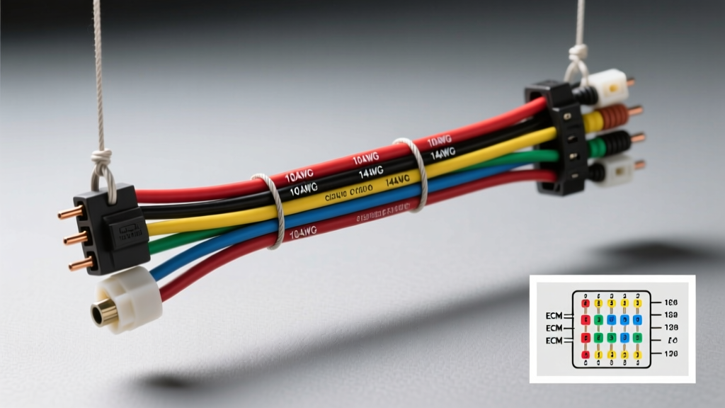
Introduction to the GM 5.7L TBI Wiring Architecture
When performing an engine swap, restoring a GMT400 truck, or diagnosing a drivability issue, understanding the 5.7 TBI wiring harness diagram is absolutely critical. The 1988-1995 General Motors 5.7L (350 CID) Throttle Body Injection (TBI) system relies on a Speed Density fuel management strategy. Unlike later Mass Air Flow (MAF) systems, the TBI ECM calculates engine load using a Manifold Absolute Pressure (MAP) sensor, engine RPM, and a pre-programmed fuel map. Because the system operates in a harsh under-hood environment, the wiring harness is subjected to extreme heat cycles, vibration, and moisture. Over time, the corrugated plastic loom becomes brittle, and the copper strands inside the insulation suffer from micro-fractures. This comprehensive walkthrough dissects the core circuits of the 5.7L TBI harness, detailing ECM pinouts, wire color codes, and real-world failure modes that generic repair manuals often overlook.
ECM Connector Pinout & Wire Color Breakdown
The heart of the 5.7L TBI system is the Delco ECM (typically part number 16198128 for 1993-1995 models). The main harness interfaces with the ECM via two 32-pin rectangular connectors: Connector C1 (Blue) and Connector C2 (Red). These connectors utilize Delphi Weather-Pack and Metri-Pack 280 series terminals. Below is the critical pinout data required for tracing the 5.7 TBI wiring harness diagram.
Connector C1 (Blue) - Power, Ground, and Ignition
| Pin | Circuit Function | Wire Color | AWG |
|---|---|---|---|
| A1 | Injector 1 Driver (Ground Switch) | Tan | 16 |
| A2 | Injector 2 Driver (Ground Switch) | Dark Green/White | 16 |
| A6 | Service Engine Soon (SES) Lamp Control | Brown/White | 18 |
| B1 | Distributor Reference Signal (Low) | Purple/White | 18 |
| B6 | Electronic Spark Timing (EST) Signal | Tan/White | 18 |
| C1 | Fuel Pump Relay Control (Ground) | Dark Green/White | 16 |
| C12 | ECM Battery Feed (Constant 12V) | Orange | 14 |
| D1 | ECM Ignition Feed (Switched 12V) | Pink/Black | 14 |
Connector C2 (Red) - Sensors and Actuators
| Pin | Circuit Function | Wire Color | AWG |
|---|---|---|---|
| D1 | MAP Sensor Signal | Dark Green | 18 |
| D7 | Throttle Position Sensor (TPS) Signal | Light Blue | 18 |
| E1 | Oxygen (O2) Sensor Signal | Purple | 18 |
| F1 | IAC Valve Coil A (Low) | Light Green/Black | 18 |
| F2 | IAC Valve Coil A (High) | Light Blue/White | 18 |
| F3 | IAC Valve Coil B (Low) | Dark Green/White | 18 |
| F4 | IAC Valve Coil B (High) | Dark Blue/White | 18 |
Sensor & Actuator Circuit Walkthrough
To properly interpret the 5.7 TBI wiring harness diagram, you must understand how the ECM processes analog sensor data and commands high-current actuators.
MAP Sensor & TPS Wiring
The MAP sensor and Throttle Position Sensor (TPS) share a common 5-Volt Reference circuit originating from the ECM (typically a Gray wire). The MAP sensor signal returns to the ECM on a Dark Green wire. A common failure mode in the GMT400 harness is the chafing of this Dark Green wire against the intake manifold or firewall, which causes a dead short to ground. This tricks the ECM into seeing maximum vacuum (high altitude), resulting in a severely lean condition and a Code 33 or 34. The TPS signal returns on a Light Blue wire. When testing the TPS, you should see a smooth voltage sweep from ~0.54V at idle to ~4.5V at wide-open throttle. Any dropouts in the oscilloscope waveform indicate internal potentiometer wear or a harness pin drag issue at the C2 connector.
Idle Air Control (IAC) Valve Stepper Motor
The TBI IAC valve is a dual-coil stepper motor, not a simple PWM solenoid. The ECM utilizes an internal quad-driver to sequentially ground the four IAC wires (Light Green/Black, Light Blue/White, Dark Green/White, Dark Blue/White) to step the pintle in or out. Because these are low-current control circuits (18 AWG), they are highly susceptible to voltage drop. If the harness ground connections at the cylinder head are corroded, the IAC pintle will lose steps, causing an erratic or hunting idle. Never apply direct 12V battery power to IAC wires during bench testing; doing so will instantly fry the ECM quad-driver.
The Fuel Pump Relay & Oil Pressure Bypass Circuit
One of the most unique and frequently misunderstood aspects of the GM TBI wiring diagram is the fuel pump power circuit. The ECM grounds the Fuel Pump Relay coil for exactly 2 seconds when the ignition is turned to the "ON" position to prime the system. Once the engine is cranking, the ECM maintains the relay ground based on the distributor reference signal. However, GM engineers included a critical fail-safe: the Oil Pressure Switch Bypass. An Orange wire feeds 12V into the oil pressure sender unit. Once oil pressure reaches approximately 4 PSI, an internal mechanical switch closes, sending 12V out through a Gray wire directly to the fuel pump. This means a truck with a failed fuel pump relay or a broken ECM fuel pump control wire will still run perfectly fine once the engine builds oil pressure. When diagnosing a "cranks but no start" TBI issue, always verify the Orange and Gray wires at the oil pressure sender block located near the distributor.
Ignition & Electronic Spark Timing (EST)
The 5.7L TBI utilizes a large-cap HEI distributor with an internal 4-pin ignition module. During cranking, the module operates in "Bypass" mode, triggering spark based on the mechanical centrifugal advance. Once the engine reaches ~400 RPM, the ECM sends a 5V logic high signal on the Purple/White Bypass wire. This switches the 4-pin module into EST mode, allowing the ECM to take full control of spark advance via the Tan/White EST wire. If the Purple/White wire is broken, or if the Pink/Black 12V ignition feed to the HEI module drops below 9V during cranking, the engine will never transition to EST mode, resulting in a severe lack of power and a Code 42.
Common Harness Failure Modes & Troubleshooting
Based on decades of field data and official GM Service Documentation from Helm Inc., the following are the most prevalent failure points in the 5.7 TBI harness:
- ECM Ground Loop (G103): The ECM grounds (Black and Black/White wires) must be terminated to a clean, bare metal surface on the cylinder head or intake manifold using a star washer. A poor ground here causes the 5V reference to float, throwing simultaneous Codes 21 (TPS High), 31 (MAP High), and 23 (MAT Low).
- Injector Connector Brittle Latch: The Metri-Pack 150 series connectors at the TBI injectors become brittle from under-hood heat. The locking tang snaps off, allowing the connector to vibrate loose, causing a lean misfire on one bank.
- ALDL Connector Pin Drag: The Assembly Line Diagnostic Link (ALDL) under the dash relies on a solid Pin B (Diagnostic Test) to Pin A (Ground) connection to flash codes. Corrosion here prevents the retrieval of historical ECM codes.
Wire Gauge & Terminal Crimping Specifications
When repairing or fabricating a custom 5.7 TBI swap harness, adhering to SAE International wiring standards (SAE J1192) is mandatory for reliability and fire prevention. Do not use solder on automotive harness connections subject to high vibration; solder joints work-harden and snap. Use open-barrel crimping tools designed for Delphi terminals.
| Circuit Type | Recommended AWG | Terminal Series | Insulation Type |
|---|---|---|---|
| 5V Reference & Sensor Signals | 18 AWG | Metri-Pack 280 | Cross-linked Polyethylene (GXL) |
| Injector Drivers & Relay Coils | 16 AWG | Weather-Pack / Metri-Pack | GXL or TXL |
| ECM Power Feeds & Main Grounds | 14 AWG (or 12 AWG) | Weather-Pack 6.3mm | TXL (High Temp) |
| ALDL & Interior Dash Wiring | 18-20 AWG | Weather-Pack 150 | PVC (Standard) |
Expert Swap & Routing Advice
When utilizing an aftermarket harness from manufacturers like Painless Performance for a 5.7L TBI swap into a non-GMT400 chassis, routing is just as critical as the pinout. Keep the high-current injector and fuel pump wires separated from the low-voltage MAP and O2 sensor signal wires by at least 3 inches to prevent electromagnetic interference (EMI). The O2 sensor signal wire (Purple) is highly susceptible to alternator whine and ignition cross-talk; it must be routed away from the HEI cap and spark plug wires. Always use split-loom tubing and high-temperature Tesa tape in the engine bay, and apply dielectric grease to all ECM and sensor connectors to prevent galvanic corrosion between the copper terminals and the tin-plated ECM pins. Mastering the 5.7 TBI wiring harness diagram ensures your Speed Density system runs flawlessly for hundreds of thousands of miles.