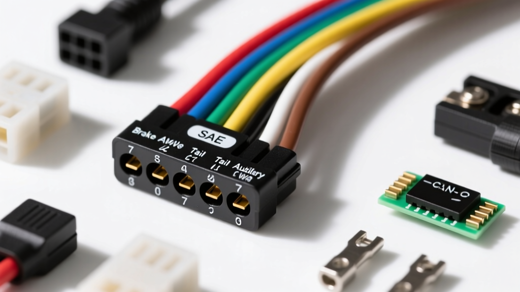
Architectural Overview of Heavy-Duty Trailer Hitch Harnesses
When upgrading from a standard 4-way flat connector to a comprehensive wiring harness for trailer hitch applications, the electrical architecture shifts from simple parallel circuits to a multi-node power distribution system. Modern heavy-duty towing requires dedicated circuits for electric trailer brakes, 12V auxiliary power, and reverse lockout solenoids. This technical deep dive explores the engineering principles behind the 7-way RV blade connector, SAE wire gauge requirements, and the integration of aftermarket harnesses with modern CAN-bus and PWM (Pulse Width Modulation) Body Control Modules (BCMs). Understanding the underlying physics and digital communication protocols of your vehicle's towing package is critical to preventing voltage drop, BCM fault codes, and catastrophic ground loop failures.
SAE and RVIA 7-Way Pinout Specifications
The 7-way RV blade connector is the undisputed standard for light-to-medium duty towing in North America. Governed by guidelines from the RV Industry Association (RVIA) and harmonized with SAE color codes, the pinout dictates not only the function of each circuit but also the required wire gauge to handle specific amperage loads safely. Below is the definitive reference chart for a heavy-duty 7-pin harness.
| Pin | Function | Standard Wire Color | Minimum AWG | Max Continuous Load |
|---|---|---|---|---|
| 1 | Ground (Chassis Bond) | White | 8 AWG | 40A |
| 2 | Electric Trailer Brakes | Blue | 10 AWG | 30A |
| 3 | Tail / Running Lights | Brown | 12 AWG | 15A |
| 4 | Right Turn / Stop | Green | 12 AWG | 15A |
| 5 | Left Turn / Stop | Yellow | 12 AWG | 15A |
| 6 | 12V Aux / Battery Charge | Black | 8 AWG | 40A |
| 7 | Reverse Lights / Solenoid | Purple | 14 AWG | 10A |
Voltage Drop Calculations and AWG Sizing
A common failure point in aftermarket harness installations is undersizing the wire gauge for the electric brake circuit (Pin 2) and the 12V auxiliary charge line (Pin 6). According to SAE J1128 Low Tension Primary Cable Standards, wire resistance increases as gauge size increases, leading to voltage drop over the physical length of the harness. In a towing scenario, the total circuit length must be calculated as a round-trip (from the tow vehicle battery, to the trailer axle brakes, and back to the ground).
The Physics of Trailer Brake Voltage Drop
Consider a 30-foot trailer. The round-trip circuit length is 60 feet. If the trailer features dual-axle electric brakes drawing a combined 15 Amps during maximum braking effort, using 12 AWG wire (which has a resistance of approximately 1.588 ohms per 1,000 feet) will result in a voltage drop of 1.43 Volts. While this seems negligible, the brake controller relies on precise voltage modulation to apply proportional braking force. A 1.43V drop on a 12V system represents a nearly 12% loss in braking efficiency.
By upgrading the blue brake wire and white ground wire to 10 AWG (0.9989 ohms per 1,000 feet) or ideally 8 AWG, the voltage drop is reduced to 0.89 Volts, ensuring the trailer brakes receive the full PWM signal from the controller. For the 12V auxiliary line (Pin 6), which is often used to charge deep-cycle trailer batteries or power winches, 8 AWG is mandatory to prevent the wire from acting as a resistor and generating excessive thermal buildup inside the harness loom.
CAN-Bus Integration and PWM Signal Isolation
Modern trucks (such as the 2015+ Ford F-150, Ram 2500, and GM Silverado HD) no longer use simple 12V analog switches for taillights and turn signals. Instead, the Body Control Module (BCM) utilizes multiplexed CAN-bus networks and Pulse Width Modulation (PWM) to monitor circuit health and prevent thermal overloads. If you splice a traditional relay-based trailer harness directly into a PWM-controlled taillight circuit, the BCM will interpret the inductive kickback from the relay coil as a short circuit, triggering a "Trailer Wiring Fault" message on the dashboard and shutting down the circuit.
Powered Isolation Modules
To properly integrate a wiring harness for trailer hitch setups on modern vehicles, you must use a powered converter module equipped with MOSFET (Metal-Oxide-Semiconductor Field-Effect Transistor) switching. These modules draw less than 5mA of signal current from the vehicle's BCM to trigger the gate, while pulling the heavy amperage load (up to 15A per circuit) directly from a dedicated 12V battery feed. This provides complete galvanic isolation between the vehicle's sensitive CAN-bus network and the harsh, electrically noisy environment of the trailer harness.
Advanced Crimping and Environmental Sealing
The physical termination of the harness wires is just as critical as the electrical design. For heavy-duty towing, standard closed-barrel ring terminals crimped with generic pliers are unacceptable. The vibration inherent in towing will cause work-hardening and eventual fracture of improperly crimped copper strands.
- Open-Barrel F-Crimps: For splicing into factory harnesses, use open-barrel crimps with a ratcheting crimper designed for non-insulated terminals. This creates a cold-weld bond between the terminal and the copper strands.
- Adhesive-Lined Heat Shrink: Every termination point must be sealed with dual-wall, adhesive-lined heat shrink (minimum 3:1 shrink ratio). When heated, the inner thermoplastic lining melts and flows into the wire strands, creating a watertight barrier that prevents capillary action from drawing moisture under the wire insulation.
- Anti-Oxidant Paste: When terminating the main 8 AWG white ground wire to the vehicle chassis, sand the paint down to bare metal, apply a layer of zinc-based anti-oxidant paste, and secure it with a stainless steel bolt and star washer to ensure a permanent, low-resistance ground plane.
Troubleshooting Decision Tree: Ground Faults and Backfeed
Even with premium components, environmental degradation can lead to complex electrical faults. Use the following diagnostic tree to isolate common trailer harness anomalies:
Symptom 1: Trailer Running Lights Flash When Turn Signals Are Activated
- Cause: Ground Loop / Backfeed. The trailer's taillight ground is corroded, causing the return current to seek an alternative path back to the tow vehicle through the turn signal circuit.
- Fix: Disconnect the trailer. Clean the primary white ground wire termination on both the tow vehicle chassis and the trailer tongue. Verify continuity between the trailer frame and the 7-pin ground pin (Pin 1); resistance must be less than 0.5 ohms.
Symptom 2: Electric Brakes Lock Up When Headlights Are Turned On
- Cause: Short between the Brown (Running Lights) and Blue (Brakes) wires, typically caused by chafing inside the harness loom near the hitch pivot point.
- Fix: Perform a megohmmeter (insulation resistance) test between the Brown and Blue circuits at the vehicle-side 7-pin connector. If resistance is below 1 Megohm, inspect the harness flex-point behind the bumper for abrasion and repair using solder-seal butt splices.
Symptom 3: BCM Throws "Trailer Disconnected" Code Despite Being Plugged In
- Cause: The BCM's continuity check relies on a specific resistance load across the lighting circuits. If the trailer uses all-LED lighting, the current draw is too low for the BCM to detect the trailer.
- Fix: Install CAN-bus compatible load resistors (typically 6-ohm, 50W) in parallel with the trailer's LED turn signal circuits, or flash the vehicle's BCM with a custom "LED Trailer" calibration file via an OBD-II programmer.
For comprehensive wiring diagrams and vehicle-specific harness routing, always consult the CURT Manufacturing Wiring Guide or your vehicle manufacturer's upfitter documentation. Proper execution of these advanced electrical principles ensures a reliable, safe, and legally compliant towing setup.