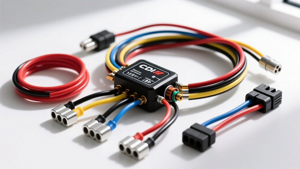
Decoding the 125cc Wiring Harness Diagram
Working on a 125cc pit bike, ATV, or dirt bike often means dealing with notoriously confusing factory electrical systems. Whether you are restoring a Honda CRF125, rebuilding a Yamaha TTR125, or rewiring a generic horizontal-engine clone (like the ubiquitous CG125 or GY6 variants), understanding the 125cc wiring harness diagram is the difference between a bike that fires up on the first kick and one that leaves you stranded with a dead battery and no spark.
Unlike modern fuel-injected motorcycles with sealed ECU looms, most 125cc carbureted machines rely on a decentralized harness connecting the stator, CDI (Capacitor Discharge Ignition), rectifier/regulator, and ignition coil. Factory diagrams are often incomplete, and wire colors can vary wildly between manufacturing batches. This practical installation guide breaks down the exact pinouts, wire color codes, and routing techniques required to install, repair, or upgrade your 125cc wiring harness correctly.
AC-CDI vs. DC-CDI: Identifying Your Harness Type
Before cutting a single zip tie, you must identify whether your 125cc engine utilizes an AC-CDI or DC-CDI system. Installing the wrong harness or CDI unit will instantly fry the ignition module.
- AC-CDI Systems: Powered directly by the stator's source coil (usually a Black/Red wire). These systems do not require a battery to generate a spark, making them ideal for kick-start-only dirt bikes. The harness routes high-voltage AC directly to the CDI.
- DC-CDI Systems: Powered by the vehicle's 12V battery (usually a Red or Black/Yellow wire). These are common on 125cc ATVs and electric-start pit bikes. The harness must route stabilized DC voltage from the rectifier/battery to the CDI.
Core Component Pinouts and Wire Color Codes
The most critical junction in any 125cc wiring harness is the CDI connector. Below is the standardized pinout matrix for the most common 6-pin DC-CDI and 5-pin AC-CDI configurations found on 125cc horizontal and vertical engines.
CDI Harness Connector Pinout Matrix
| Pin # | DC-CDI Wire Color | AC-CDI Wire Color | Function / Destination | Signal Type |
|---|---|---|---|---|
| 1 | Blue/White | Blue/White | Pulse Pickup Coil (Trigger) | Low Voltage AC Signal |
| 2 | Green | Green | System Ground | Ground (0V) |
| 3 | Black/White | Black/White | Kill Switch / Ignition Off | Ground Trigger |
| 4 | Red (12V Battery) | Black/Red (Stator Source) | Primary Power Supply | 12V DC / High V AC |
| 5 | Black/Yellow | Black/Yellow | Output to Ignition Coil | High Voltage DC Pulse |
| 6 | N/C or Spare | N/A | Rev Limiter / Tachometer | Signal Output |
Stator to Harness Routing
The stator exits the engine case with a bundle of 4 to 6 wires. Correctly mapping these to the main harness is where most DIY mechanics fail.
- Yellow: AC Lighting Output (Routes to Rectifier AC input and headlight switch).
- White: AC Charging Output (Routes to Rectifier AC input to charge the battery).
- Blue/White: Pulse Pickup (Routes directly to CDI Pin 1).
- Green: Stator Ground (Must be bolted to a clean, bare metal point on the engine case).
Step-by-Step Harness Installation Guide
Follow this sequence to ensure a reliable, moisture-resistant installation that withstands the heavy vibrations inherent to 125cc single-cylinder engines.
- Prep the Engine Grounds: Before plugging in the harness, locate the main engine ground point on the cylinder head or crankcase. Use a wire wheel to remove all paint, powder coating, and corrosion. Apply a thin layer of dielectric grease after securing the ring terminal to prevent oxidation.
- Route the Stator Wires First: Feed the stator wires through the frame's designated grommet hole. Never force wires through sharp metal edges without a rubber grommet. Secure the stator loom to the frame using UV-resistant nylon zip ties, keeping at least 3 inches of clearance from the exhaust header.
- Install the Rectifier/Regulator: Mount the rectifier in an area with direct airflow (usually near the steering stem or under the seat). Connect the White and Yellow stator wires to the rectifier's AC inputs, and the Red/Green wires to the battery positive and chassis ground.
- Connect the CDI and Coil: Plug the CDI harness connector in until you hear a definitive click. Route the Black/Yellow ignition coil wire away from the spark plug wire to prevent electromagnetic interference (EMI), which can cause misfires at high RPMs.
- Loom and Secure: Wrap the entire main harness in split-loom tubing or friction tape. Friction tape (like Tesa 51036) is preferred for off-road 125cc bikes as it prevents the harness from vibrating against the frame and creating a rattling noise.
Wire Gauge (AWG) Specifications and Upgrades
Factory 125cc wiring harnesses often use undersized wire to cut costs, leading to voltage drops and dim headlights. When repairing or fabricating a custom harness, adhere to SAE J1128 standards for low-tension primary automotive cable. Upgrading to GXL or TXL cross-linked polyethylene insulated wire provides superior heat resistance near the engine.
| Circuit Function | Factory AWG (Typical) | Recommended Upgrade AWG | Max Amperage Capacity |
|---|---|---|---|
| Stator to Rectifier (AC) | 18 AWG | 16 AWG | 10A - 15A |
| CDI Trigger / Signals | 20 AWG | 18 AWG | 5A |
| Main Battery Feed / Starter | 14 AWG | 10 AWG | 30A - 50A |
| Lighting / Accessories | 18 AWG | 16 AWG | 10A |
Real-World Troubleshooting: The Melted Stator Plug
The most common failure point on any 125cc ATV or pit bike wiring harness is the 4-pin plastic connector where the stator meets the main harness. Due to high AC amperage and engine heat, the factory pins oxidize, increase resistance, and literally melt the plastic housing, causing a total loss of electrical power.
The Expert Fix: Bypass and Solder
Do not simply replace the plastic connector; it will melt again. Instead, bypass the plug entirely.
- Cut the melted connector off both the stator side and the harness side.
- Strip back 1/2 inch of insulation on the Yellow, White, Blue/White, and Green wires.
- Twist the corresponding wires together, apply rosin-core solder, and seal the joint using marine-grade adhesive-lined heat shrink tubing. The adhesive melts and creates a waterproof seal that prevents green corrosion from wicking up into the stator windings.
No-Spark Diagnostic Decision Tree
If you have installed the harness according to the 125cc wiring harness diagram but the engine lacks spark, use this multimeter diagnostic tree:
- Symptom: No spark, CDI gets warm.
- Cause: Shorted ignition coil or Pin 5 (Black/Yellow) is grounding out against the frame.
- Fix: Check continuity between Pin 5 wire and chassis ground. It should read 'OL' (Open Loop).
- Symptom: No spark, CDI stays cold.
- Cause: No power reaching Pin 4. (Dead battery on DC-CDI, or blown stator source coil on AC-CDI).
- Fix: Test DC voltage at Pin 4 with the key ON (DC-CDI). For AC-CDI, test AC voltage at the Black/Red stator wire while kicking the engine (should read 50V+ AC).
- Symptom: Intermittent spark at high RPM.
- Cause: Failing pulse pickup coil or excessive air gap between the pickup and the flywheel magneto.
- Fix: Measure the air gap with a feeler gauge (spec is typically 0.4mm - 0.6mm). Test pickup coil resistance (should be 110-180 ohms per ISO 6722 road vehicle cable standards and OEM service manuals).
Final Harness Routing and Safety Checks
Before reinstalling the seat and plastics, perform the 'shake test.' Grab the main harness loom and shake it vigorously while the engine is idling. If the engine stumbles or dies, you have a loose pin inside a connector or a wire chafing against the frame. Always use a small dab of RTV silicone inside the back of rubber connector boots to prevent water intrusion, and ensure your kill switch circuit (Pin 3) is functioning correctly before taking the bike off the stand. A properly installed 125cc wiring harness should provide years of reliable, maintenance-free service.