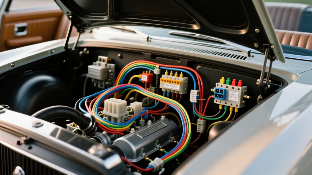
Why Upgrade to a 22 Circuit Wiring Harness?
When performing a restomod on a classic muscle car, hot rod, or vintage truck, the factory electrical system is almost always the weakest link. Original cloth-insulated or early PVC wiring becomes brittle, resistance increases, and glass AGC fuses offer poor protection against modern electrical faults. Furthermore, adding fuel injection, electric cooling fans, and modern audio systems easily overwhelms a stock 6-circuit or 12-circuit factory harness.
Upgrading to a universal 22 circuit wiring harness provides the perfect balance of capacity and simplicity for a standard restomod build. It supplies dedicated, properly fused circuits for all essential vehicle functions while utilizing modern ATO/ATC blade fuses and integrated relay triggers. By adhering to SAE J1128 standards for low-tension primary cable, modern harness kits utilize cross-linked polyethylene (XLPE) insulation (TXL/GXL wire), which withstands under-hood temperatures up to 125°C (257°F) and resists automotive fluids.
Anatomy of a Modern 22-Circuit Universal Harness
A high-quality 22 circuit wiring harness routes from a centralized, firewall-mounted fuse panel. The circuits are pre-terminated with sufficient length for full-size passenger cars and light trucks. Below is the standard circuit allocation, wire gauge, and SAE-compliant color coding for a comprehensive restomod harness.
| Circuit # | Function | AWG Size | SAE Color Code | Fuse Rating |
|---|---|---|---|---|
| 1 | Headlights (Low/High) | 12 AWG | Tan / Yellow | 20A ATO |
| 2 | Parking / Tail Lights | 14 AWG | Brown | 15A ATO |
| 3 | Left Turn Signal | 14 AWG | Dark Green | 10A ATO |
| 4 | Right Turn Signal | 14 AWG | Light Green | 10A ATO |
| 5 | Brake Lights | 14 AWG | White | 15A ATO |
| 6 | Horn | 10 AWG | Purple | 20A ATO |
| 7 | Electric Wipers | 12 AWG | Blue | 15A ATO |
| 8 | Radio / Memory | 14 AWG | Orange | 10A ATO |
| 9 | Ignition Switch (Run) | 12 AWG | Pink | 20A ATO |
| 10 | Ignition Switch (Start) | 10 AWG | Red w/ Stripe | 30A MAXI |
| 11 | Instrument Gauges | 14 AWG | Gray | 5A ATO |
| 12 | Backup Lights | 14 AWG | Light Green | 10A ATO |
| 13 | Electric Fuel Pump | 12 AWG | Red | 20A ATO |
| 14 | Electric Cooling Fan | 10 AWG | Dark Blue | 30A MAXI |
| 15 | A/C Compressor Clutch | 14 AWG | Dark Green | 10A ATO |
| 16 | Dash / Interior Lights | 16 AWG | Brown w/ White | 5A ATO |
| 17 | Power Windows (Left) | 12 AWG | Light Blue | 20A ATO |
| 18 | Power Windows (Right) | 12 AWG | Tan | 20A ATO |
| 19 | EFI / ECU Main Power | 10 AWG | Red | 30A MAXI |
| 20 | Accessory / Cigarette Lighter | 12 AWG | Yellow | 20A ATO |
| 21 | Dome / Courtesy Lights | 14 AWG | White | 10A ATO |
| 22 | Flasher / Hazard Module | 14 AWG | Brown | 15A ATO |
Relay Integration: Solving the Headlight Voltage Drop
One of the most critical advantages of installing a modern 22 circuit wiring harness is the integration of headlight and horn relays. In classic vehicles, the full amperage load of the headlights (often 10 to 15 amps) travels through the firewall, into the dash switch, and back out to the lamps. This causes severe voltage drop, dim lights, and melted switch contacts.
Modern harnesses utilize standard Bosch-style 5-pin automotive relays. The factory headlight switch now only carries a fraction of an amp to trigger the relay coil (Terminal 86). The heavy current flows directly from the battery, through a 30A MAXI fuse, into the relay's common terminal (Terminal 30), and out to the headlights via Terminal 87. According to SAE J558 headlamp wiring standards, this ensures the lamps receive a full 14.2V at the socket, maximizing lumen output and eliminating the risk of thermal degradation at the switch.
Routing Strategy and Firewall Pass-Through
Proper routing is just as important as circuit allocation. When feeding the engine bay portion of the harness through the firewall, always use a dedicated, reinforced rubber grommet. Never allow wire insulation to rest against bare, stamped sheet metal, as chassis vibration will eventually slice through the TXL insulation and cause a dead short.
Clearance Specifications
- Exhaust Manifolds / Headers: Maintain a minimum clearance of 6 inches. If routing near exhaust is unavoidable, use high-temp silicone fiberglass sleeving rated for 500°F.
- Steering Shafts & Linkage: Secure the harness at least 3 inches away from any moving mechanical linkage using nylon cable ties or Tesa cloth tape.
- Sharp Edges: Apply adhesive-backed closed-cell foam tape to any sheet metal edges the harness may contact.
Terminations and Connector Selection
While soldering is acceptable for static, interior connections, it is strictly prohibited in high-vibration engine bay environments. Solder wicks into the wire strands, creating a rigid point that will inevitably snap under harmonic engine vibration. Instead, utilize MIL-spec open-barrel crimps using a high-quality ratcheting crimp tool (such as those conforming to M22520 standards).
For under-hood connections, rely on sealed connector systems like Weather-Pack or Metri-Pack 150/280 series. These connectors feature silicone secondary locks and rubber cavity plugs that prevent moisture ingress and terminal oxidation. Always finish bare wire splices with dual-wall, adhesive-lined heat shrink tubing. The inner wall melts and flows into the wire strands, creating a waterproof seal that prevents capillary action from drawing moisture under the insulation.
Grounding: The Root of 90% of Electrical Gremlins
A 22 circuit wiring harness will only perform as well as its ground paths. Classic unibody vehicles and body-on-frame trucks suffer from poor factory grounding due to rust, rubber body mounts, and painted surfaces. Do not rely on daisy-chained grounds. Implement a dedicated 'star grounding' strategy:
- Engine to Chassis: Run a minimum 4 AWG flexible braided ground strap from the alternator bracket or intake manifold directly to the chassis or frame rail.
- Chassis to Body: Run a 6 AWG ground strap from the frame to the firewall or body tub to ensure the lighting and dash circuits have a low-resistance return path to the battery.
- Cylinder Head to Fire Wall: Use a 10 AWG braided strap to ground the engine block to the firewall, ensuring the starter motor and ignition system do not seek a ground path through the throttle cable or choke linkage.
For expert guidance on high-amperage charging and grounding systems, consult the technical archives at MAD Enterprises, which detail the necessity of upgrading the main battery charge wire to 4 AWG or larger when running modern 100+ amp alternators.
Troubleshooting Common Installation Faults
Even with a premium 22 circuit wiring harness, installation errors can occur. Use a digital multimeter (DMM) to perform voltage drop tests rather than relying solely on test lights. A test light will illuminate even if a circuit has enough resistance to drop 4 volts, whereas a DMM will reveal the exact voltage loss.
- Symptom: Headlights dim when the electric cooling fan engages.
Cause: Shared ground path or undersized main battery feed wire.
Fix: Verify the fan relay is grounded directly to the chassis, and ensure the main 4 AWG battery feed to the fuse panel is free of corrosion. - Symptom: Fuel pump relay clicks rapidly but pump does not run.
Cause: High resistance on the relay coil trigger wire (Terminal 86) or poor ground on Terminal 85.
Fix: Check for voltage drop across the ignition switch feed and clean the chassis ground point for the relay block.
Conclusion
Installing a 22 circuit wiring harness transforms a classic vehicle from an electrical liability into a reliable, modern-driving machine. By utilizing TXL wire, sealed connectors, integrated relays, and meticulous grounding practices, you ensure that your restomod's lighting, fuel injection, and accessory systems operate flawlessly for decades to come.