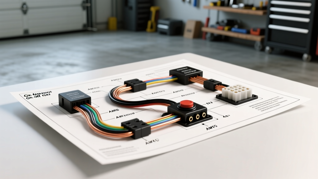
Introduction to 12V Automotive Switch Circuits
When modifying a vehicle with aftermarket accessories like LED light bars, air compressors, or auxiliary cooling fans, understanding the fundamental wiring diagram on off switch configuration is critical. Many beginners make the dangerous mistake of routing full accessory amperage directly through a dashboard toggle switch. This not only risks melting the switch housing but can also lead to catastrophic electrical fires. A proper automotive wiring diagram on off switch setup relies on a low-amperage control circuit to trigger a high-amperage relay, keeping heavy current out of the vehicle cabin and steering column. In this beginner-friendly guide, we will break down the exact pinouts, AWG wire sizing, and routing strategies required to build a safe, reliable 12V switched circuit that meets professional automotive standards.
Anatomy of a Standard SPST Toggle and Rocker Switch
The most common switch used in auxiliary automotive wiring is the Single Pole Single Throw (SPST) switch. Whether you are using a classic metal toggle switch or a modern marine-grade LED rocker switch, the internal mechanism is designed to simply bridge or break a single electrical connection. However, illuminated rocker switches introduce a third pin to power the internal LED indicator. Understanding these pinouts is the first step in deciphering any wiring diagram on off switch schematic.
| Switch Type | Pin Count | Pin Functions | Best Application |
|---|---|---|---|
| Standard SPST Toggle | 2 Pins | 1: Power In, 2: Load Out | Simple relay triggering, hidden switches |
| Illuminated SPST Rocker | 3 Pins | 1: Power In, 2: Load Out, 3: LED Ground | Dashboard light bars, winch controls |
| SPDT Toggle (On/Off/On) | 3 Pins | 1: Load A, 2: Power In, 3: Load B | Reversing winches, dual-speed fans |
Why You Must Use a Relay with Your On/Off Switch
A standard automotive toggle or rocker switch is typically rated for 10 to 20 amps. While this might seem sufficient for a 15-amp light bar, running continuous high current through the switch and the firewall into the cabin generates excessive heat and voltage drop. Furthermore, pulling heavy-gauge wire through the vehicle firewall is difficult and compromises the cabin seal. By integrating a standard Bosch-style ISO mini relay (5-pin), your switch only needs to carry the minimal current required to energize the relay coil (typically less than 0.2 amps). The heavy current is then routed directly from the battery to the accessory under the hood, bypassing the cabin entirely.
Understanding the ISO Mini Relay Pinout
The standard 5-pin automotive relay features specific DIN numbering that you will see on almost every professional wiring diagram on off switch layout:
- Pin 86: Coil Power (Trigger from your switch)
- Pin 85: Coil Ground (Completes the control circuit)
- Pin 30: Common Power Input (Heavy 12V+ from battery)
- Pin 87: Normally Open Output (Sends power to accessory when relay clicks)
- Pin 87a: Normally Closed Output (Unused in standard on/off accessory setups)
Step-by-Step: Wiring Diagram On Off Switch with Relay Integration
To build a safe and reliable circuit, you must divide your wiring into two distinct paths: the Control Circuit and the Load Circuit. Always disconnect the negative battery terminal before beginning any automotive electrical work.
Phase 1: The Control Circuit (Low Amperage)
The control circuit powers the switch and triggers the relay. Because this circuit carries less than 1 amp, you can safely route it through the firewall into the driver cabin.
- Power to Switch: Run 18 AWG primary wire from a fused ignition source (or constant 12V battery source, depending on preference) to Pin 1 of your switch. Install a 3-amp ATO blade fuse within 6 inches of the power source.
- Switch to Relay: Run 18 AWG wire from Pin 2 of the switch, through the firewall using a rubber grommet, and connect it to Relay Pin 86.
- Relay Ground: Run 18 AWG wire from Relay Pin 85 to a clean, bare-metal chassis ground under the hood. Use a ring terminal and secure it with a machine screw, applying dielectric grease to prevent corrosion.
- Switch Illumination (If applicable): If using a 3-pin illuminated rocker switch, run 18 AWG wire from Pin 3 to a chassis ground inside the cabin.
Phase 2: The Load Circuit (High Amperage)
The load circuit handles the heavy current required by the accessory. This entire circuit should remain under the hood.
- Battery to Relay: Run 12 AWG or 10 AWG wire from the positive battery terminal to Relay Pin 30. Install a high-amperage fuse (e.g., 30-amp Maxi or ANL fuse) within 18 inches of the battery terminal to protect the entire wire run.
- Relay to Accessory: Run 12 AWG wire from Relay Pin 87 to the positive input of your accessory (e.g., LED light bar).
- Accessory Ground: Ground the accessory directly to the chassis using 12 AWG wire and a heavy-duty ring terminal.
Wire Color Codes and AWG Specifications
Adhering to standard automotive wire color codes ensures that any technician or future owner can easily troubleshoot your wiring diagram on off switch setup. According to SAE J1128 standards for low-tension primary cable, maintaining color consistency prevents dangerous reverse-polarity mistakes.
| Circuit Segment | Recommended AWG | Standard Color Code | Max Ampacity (Engine Bay) |
|---|---|---|---|
| Battery to Relay (Pin 30) | 12 AWG or 10 AWG | Red (Heavy Gauge) | 30A - 40A |
| Relay to Accessory (Pin 87) | 12 AWG or 10 AWG | Red or Blue | 30A - 40A |
| Battery to Switch (Control) | 18 AWG or 16 AWG | Red (Standard) | 5A - 10A |
| Switch to Relay (Pin 86) | 18 AWG or 16 AWG | Yellow or Orange | 5A - 10A |
| Grounds (Pins 85, Acc, LED) | 18 AWG to 10 AWG | Black | Matches Circuit Load |
Termination Standards: Crimping vs. Soldering
A common beginner mistake is soldering automotive wire connections. While soldering works well in household electronics, the high-vibration environment of a vehicle engine bay will cause solder joints to fatigue, crack, and eventually fail due to wire wicking and brittleness. Furthermore, soldered joints trap moisture, leading to green copper corrosion. Professional automotive electricians rely on high-quality mechanical crimps. Use a ratcheting crimp tool to secure non-insulated nickel-plated terminals, and finish the connection with adhesive-lined dual-wall heat shrink tubing. This provides an IP67 waterproof seal that is impervious to pressure washing and engine bay temperatures. For high-end accessory connections, consider using Deutsch DT series connectors, which offer superior environmental sealing and vibration resistance compared to standard spade terminals.
Troubleshooting Decision Tree
If your accessory fails to power on, use a digital multimeter to trace the wiring diagram on off switch circuit using this logical sequence:
- Symptom: Switch LED illuminates, but accessory does not turn on.
Cause: Control circuit is functional, but load circuit has a fault.
Fix: Check the high-amp fuse near the battery. Use a multimeter to test for 12V at Relay Pin 30. If present, listen for the relay click. If the relay clicks but no power reaches the accessory, test Relay Pin 87 for continuity and check the accessory chassis ground for voltage drop. - Symptom: Relay clicks rapidly or chatters.
Cause: Insufficient current reaching the relay coil, often due to a poor ground at Pin 85 or a high-resistance connection at the switch.
Fix: Clean the chassis ground point to bare metal. Check for voltage drop across the switch contacts while depressed. - Symptom: Switch LED does not illuminate, accessory does not turn on.
Cause: Control circuit lacks power.
Fix: Test for 12V at the input side of the switch fuse. If the fuse is blown, inspect the wire routing through the firewall for pinched insulation causing a short to ground.
Authoritative References
For further reading on automotive electrical standards and relay specifications, consult the following resources:
- SAE International - SAE J1128: Low Tension Primary Cable
- Littelfuse - Mini ISO Automotive Relay Datasheet
- Painless Performance Products - Automotive Wiring Manuals
By adhering to these fundamental principles, your wiring diagram on off switch installations will remain safe, reliable, and capable of withstanding the harsh conditions of the automotive environment.