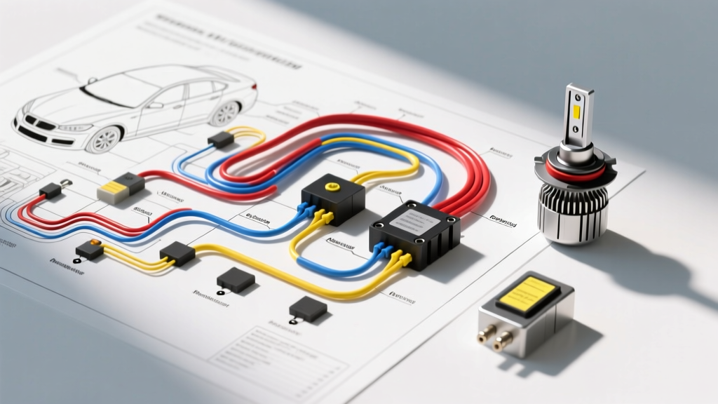
Introduction: The Electrical Demands of HID Headlights
Upgrading from standard halogen bulbs to High-Intensity Discharge (HID) xenon lighting is one of the most effective ways to improve nighttime visibility. However, HIDs are not simple plug-and-play replacements. While a standard 9006 halogen bulb draws a steady 55 watts (approximately 4.5 amps), an HID ballast requires a massive 20-amp surge for the initial 25,000-volt ignition strike, followed by a steady 3.5 to 5.0 amps during runtime. If you attempt to power aftermarket HID ballasts directly through your vehicle's original equipment manufacturer (OEM) headlight wiring, you will almost certainly experience severe voltage drop, melted factory headlight switches, or premature ballast failure.
To execute a safe and reliable installation, you must bypass the factory headlight circuit's power delivery and use it solely as a low-current trigger signal. This complete wiring diagram for HID lights walkthrough details the proper architecture of a heavy-duty relay harness, ensuring your ballasts receive clean, uninterrupted 12V DC power directly from the battery or alternator.
The Core Architecture: Standard Bosch-Style Relay Integration
The foundation of any proper HID wiring diagram is the standard ISO 7588 (Bosch-style) 4-pin relay. This electromechanical switch allows a low-current OEM signal to control a high-current power circuit. According to Hella automotive technical documentation, utilizing a relay isolates the sensitive factory body control module (BCM) or headlight switch from the heavy inductive loads generated by HID igniters.
DIN 72552 Relay Pinout Configuration
Understanding the relay terminals is critical before routing your harness. The industry-standard DIN 72552 numbering system dictates the following pin functions:
| Pin Number | Function | Wire Gauge (AWG) | Connection Point |
|---|---|---|---|
| 30 | Common / Main Power Input | 10 AWG | 12V+ Battery Post (via 30A Fuse) |
| 87 | Normally Open (NO) Output | 12 AWG | Y-Splitter to Left & Right Ballasts |
| 85 | Relay Coil Ground | 14 AWG | True Chassis Ground or Battery Negative |
| 86 | Relay Coil Trigger (Positive) | 18 AWG | OEM Headlight Positive Wire (Low Beam) |
Wire Gauge Specifications and SAE Compliance
When building or modifying an HID relay harness, selecting the correct American Wire Gauge (AWG) is non-negotiable. Undersized wiring will cause resistance, leading to voltage drop at the ballast. HID ballasts require a minimum of 11.5V to strike the arc and maintain the plasma state; anything less will result in flickering or failure to ignite. All primary automotive cable should meet or exceed SAE J1128 standards for low-tension primary cable, ensuring the insulation can withstand under-hood temperatures up to 125°C (257°F) and resist exposure to oil, grease, and battery acid.
HID Harness Material Specifications
| Circuit Segment | Recommended AWG | Stranding | Insulation Type | Protection |
|---|---|---|---|---|
| Battery to Relay (Pin 30) | 10 AWG | Multi-strand copper | Cross-linked PE (XLPE) | Split loom, 30A ATO Fuse |
| Relay to Ballasts (Pin 87) | 12 AWG | Multi-strand copper | PVC or XLPE | Split loom, tape wrap |
| OEM Trigger Tap (Pin 86) | 18 AWG | Multi-strand copper | PVC | Heat shrink, T-tap or solder |
| Ballast to Bulb (AMP/D2S) | OEM 16 AWG | Silicone shielded | High-Voltage Silicone | Braided metal shield (EMI) |
Step-by-Step Wiring Walkthrough
Step 1: Main Power and Fuse Placement
Begin by routing the 10 AWG main power wire from the positive battery terminal to the relay's Pin 30. Critical Rule: The 30A ATO blade fuse must be installed within 6 to 8 inches of the battery post. In the event of a short circuit or a ballast internal failure, placing the fuse close to the power source ensures the entire length of the harness remains protected. Use a marine-grade heat-shrink ring terminal with a 3/8-inch inner diameter to secure the connection to the battery post, applying a thin layer of dielectric grease to prevent galvanic corrosion.
Step 2: Establishing a True Ground
Pin 85 requires a solid ground to energize the relay coil. Do not rely on painted sheet metal or strut tower bolts, as these often yield high resistance. Locate a dedicated factory grounding stud on the chassis or engine block. If you must create a new ground point, drill a pilot hole, tap it for an M6 or M8 bolt, and use a star washer to bite through the metal surface for a zero-ohm connection. Sand away any paint or undercoating around the contact patch, and seal the terminal with liquid electrical tape after tightening to 10 Nm (88 in-lbs).
Step 3: Tapping the OEM Trigger Signal
The 18 AWG trigger wire connects to Pin 86. You must tap into the positive low-beam wire at the OEM headlight connector (e.g., H4, H7, or H11). Use a high-quality insulated piercing connector or, preferably, strip a small section of the OEM wire, solder the 18 AWG tap wire, and seal it with adhesive-lined dual-wall heat shrink. When the factory headlight switch is activated, 12V flows through this thin wire, energizing the relay coil and closing the high-current contact between Pin 30 and Pin 87.
Step 4: Ballast Routing and High-Voltage Connections
Route the 12 AWG output wire from Pin 87 to a weatherproof Y-splitter, which feeds the AMP or D2S input connectors on the left and right ballasts. Ensure the ballasts are mounted in a dry, well-ventilated area away from exhaust manifolds and moving suspension components. The high-voltage D2S/D2R output cables connecting the ballast to the xenon bulb carry up to 25,000 volts. These must never be cut, spliced, or bent at sharp angles, as compromising the silicone insulation will result in arcing against the chassis.
Advanced Troubleshooting: CANBUS and EMI Failure Modes
Modern vehicles utilize complex multiplexed networks and Body Control Modules (BCMs) to monitor exterior lighting. When installing an HID wiring diagram on a late-model vehicle (typically 2010 and newer), you may encounter specific electrical anomalies.
CANBUS PWM Flickering
Many manufacturers (including Chrysler, Dodge, Volkswagen, and GM) use Pulse Width Modulation (PWM) to control headlight circuits. Instead of sending a steady 12V DC signal, the BCM rapidly pulses the voltage (often between 200Hz and 400Hz) to monitor bulb continuity and extend filament life. While a halogen filament's thermal inertia masks this pulsing, an HID ballast's microprocessor will interpret the PWM signal as a rapidly switching on/off command, resulting in severe strobing or failure to ignite. Solution: Install a CANBUS decoder (a capacitor/resistor matrix) inline between the OEM trigger wire and Pin 86, or wire the relay trigger directly to a switched 12V ignition source in the fuse box using an add-a-circuit tap.
Radio Frequency Interference (RFI)
The high-voltage ignition strike generated by the HID ballast's internal transformer produces significant Electromagnetic Interference (EMI). If your AM/FM radio experiences static or your keyless entry fob loses range when the headlights are on, the ballast is leaking RFI. Solution: Ensure you are using premium, digitally ballasted units with internal metal shielding. Snap ferrite core chokes onto the 12V input wires and the high-voltage D2S cables as close to the ballast housing as possible to suppress high-frequency noise.
One-Sided Ignition Delay
If the driver-side headlight ignites instantly but the passenger-side takes multiple attempts or flickers, you are experiencing voltage drop on the 12 AWG Y-splitter harness. The initial 20A surge required by the second ballast drops the voltage below the 11.5V threshold. Solution: Upgrade the harness to a dual-relay setup, where each ballast has its own dedicated relay, 10 AWG power feed, and 30A fuse, triggered simultaneously by the single OEM signal wire.
Conclusion
A properly executed wiring diagram for HID lights guarantees maximum lumen output, protects your vehicle's sensitive factory electronics, and ensures the longevity of your aftermarket ballasts and xenon capsules. By adhering to SAE wire standards, utilizing DIN-standard relays, and addressing modern CANBUS PWM signals, you transform a complex electrical upgrade into a reliable, factory-grade lighting system. Always verify all continuity and resistance with a digital multimeter before applying power to the HID igniters for the first time.