The Restomod ABS Upgrade Challenge
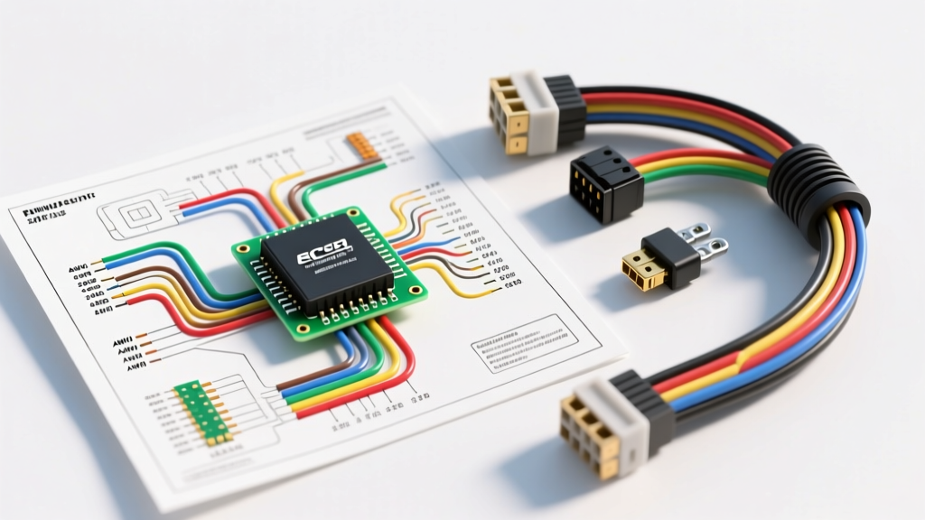
Integrating modern anti-lock braking systems into classic muscle cars, hot rods, and LS-swapped restomods is one of the most significant safety and performance upgrades a builder can undertake. While classic proportioning valves and manual boosters offer nostalgic pedal feel, they cannot match the threshold braking and yaw control of a modern Electronic Brake Control Module (EBCM). When planning a custom brake swap, obtaining and correctly interpreting the wiring ABS control module diagram is the critical first step to ensuring your system functions safely without throwing catastrophic diagnostic trouble codes (DTCs).
For many high-horsepower street and track builds, the GM 38-pin EBCM (commonly sourced from 1999-2006 GMT800 trucks and SUVs like the Silverado and Tahoe) is the gold standard. It is robust, handles high-pressure hydroboost systems, and is widely available in salvage yards. However, wiring this module outside of its original factory harness requires a deep understanding of its pinout, power requirements, and sensor signaling. This guide breaks down the exact wiring schematics, AWG requirements, and modification strategies needed to run a GM 38-pin EBCM in a standalone or custom-harness environment.
Power and Ground Circuit Requirements
The most common failure point in custom ABS installations is inadequate power delivery. The EBCM houses the solenoid valves and the hydraulic pump motor. During a hard ABS event, the pump motor can draw a peak stall current of up to 50 amps, while the solenoids draw an additional 15 to 20 amps. If your wiring cannot handle this transient load, the voltage at the module will drop below 10.5V, causing the EBCM to abort the ABS event and default to base braking.
AWG and Routing Specifications
- Battery Feed (Pin 25): Requires a dedicated 10 AWG (or 8 AWG for long runs over 8 feet) wire routed directly from the battery positive terminal or main distribution block. This circuit must be protected by a 60A maxi-fuse located within 18 inches of the power source.
- Ignition Feed (Pin 13): Requires 12 AWG wire connected to a keyed 12V ignition source. This wakes up the EBCM logic board and performs the initial bulb check and solenoid test upon startup.
- Grounds (Pins 14 and 38): Both ground circuits must be wired using 10 AWG wire. Do not daisy-chain these grounds with other accessories. They must be ring-terminated and bolted directly to a clean, bare metal point on the chassis or engine block. According to HELM Inc. GM Service Documentation, ground stud torque specifications for M6 hardware should be set to 10 Nm (89 lb-in) to ensure low-resistance continuity.
38-Pin EBCM Connector Pinout and Wire Color Chart
The GM 38-pin EBCM utilizes a weather-sealed Aptiv (formerly Delphi) GT280 series connector. When building a custom harness, you must use the correct GT280 female terminals and silicone cavity plugs to maintain the IP67 waterproof rating. Below is the essential pinout for the primary power, ground, and wheel speed sensor circuits.
| Pin | Circuit Function | OEM Wire Color | Min AWG | Notes / Modification Tips |
|---|---|---|---|---|
| 25 | Battery 12V Constant | Red | 10 | Direct to battery; 60A Maxi-Fuse |
| 13 | Ignition 12V Switched | Pink | 12 | Key-on/run 12V source |
| 14 | Logic & Pump Ground | Black | 10 | Dedicated chassis ground |
| 38 | Logic & Pump Ground | Black | 10 | Dedicated chassis ground |
| 1 | Left Front WSS High | Dark Green | 20 | Twisted pair with Pin 2 |
| 2 | Left Front WSS Low | Yellow | 20 | Twisted pair with Pin 1 |
| 3 | Right Front WSS High | Light Blue | 20 | Twisted pair with Pin 4 |
| 4 | Right Front WSS Low | Tan | 20 | Twisted pair with Pin 3 |
| 7 | Class 2 Serial Data | Dark Green/White | 22 | Requires bypass for standalone |
| 24 | Brake Switch Signal | White | 18 | 12V from brake pedal switch |
Wheel Speed Sensor Wiring: Twisted Pair & Shielding
The GMT800 EBCM relies on Variable Reluctance (VR) wheel speed sensors. Unlike modern Hall-effect sensors that output a digital square wave, VR sensors generate an analog AC sine wave whose frequency and amplitude increase with wheel speed. Because these analog signals are highly susceptible to Electromagnetic Interference (EMI) from ignition coils, alternators, and fuel injectors, proper wiring techniques are non-negotiable.
According to SAE J2264 standards for wheel speed sensors, VR sensor signals must be routed using a twisted pair configuration. You must use 20 AWG stranded copper wire and maintain a twist rate of at least 1 to 2 twists per inch along the entire length of the harness. This twisting ensures that any EMI induced into the wire affects both the High and Low signal wires equally, allowing the EBCM's differential amplifier to cancel out the noise (Common Mode Rejection).
If your harness must pass near high-voltage ignition wires or the alternator, you should wrap the twisted pair in a braided copper shielding sleeve. Critical Rule: The shield drain wire must be grounded only at the EBCM connector end. Grounding the shield at the wheel hub end will create a ground loop, turning your shield into an antenna that will induce alternator whine directly into the sensor signal, resulting in erratic ABS activation at highway speeds.
Bypassing Serial Data for Standalone ABS Operation
One of the most significant hurdles when reading a factory wiring ABS control module diagram for a custom build is the Class 2 Serial Data line (Pin 7). In a factory vehicle, the EBCM communicates constantly with the Powertrain Control Module (PCM) and Body Control Module (BCM). If the EBCM does not detect valid Class 2 data packets upon startup, it assumes a network failure, sets a U1000 DTC, illuminates the ABS dash warning light, and in some calibrations, disables the ABS functionality entirely.
For restomods running carburetors or standalone engine management systems (like Holley Terminator X or MegaSquirt), there is no factory PCM to talk to the ABS module. To bypass this, builders have two primary options:
- The Relay Bypass Method: While this doesn't trick the EBCM into thinking a PCM is present, it prevents the ABS system from disabling itself. By wiring a standard 4-pin automotive relay triggered by the brake light switch, you can interrupt the ground path to the dash ABS indicator bulb. The EBCM may still log a U1000 code internally, but the system will continue to function in base ABS mode, and the dash light will remain off.
- Standalone CAN/Class 2 Emulator: For a cleaner, fully integrated solution, aftermarket companies now offer Serial Data simulators. These small microcontrollers plug into Pin 7 and broadcast the exact hexadecimal wake-up and keep-alive messages the EBCM expects from a GM PCM, satisfying the network check and keeping the system fully active without logging network DTCs.
Common Modification Pitfalls and Troubleshooting
Even with a perfect wiring ABS control module diagram, physical installation variables can cause system failures. Use this diagnostic decision tree to troubleshoot common post-swap issues.
Symptom: ABS Pump Runs Continuously After Key-On
- Cause 1: Missing or high-resistance ground on Pin 14 or 38. The EBCM logic board fails to complete the solenoid test circuit and defaults the pump relay to 'ON'. Fix: Perform a voltage drop test across the ground wires while the pump is running. Any reading over 0.1V indicates a bad ground.
- Cause 2: Ignition wire (Pin 13) back-feeding from another accessory. Fix: Ensure the ignition source is isolated and drops to 0V immediately when the key is turned off.
Symptom: Intermittent ABS Activation on Smooth Roads (C0035-C0050 DTCs)
- Cause 1: Incorrect VR Sensor Air Gap. The GMT800 sensors require an air gap between the sensor tip and the reluctor ring of 0.5mm to 1.5mm. If the gap is too wide, the signal amplitude drops below the EBCM's 100mV threshold at low speeds, causing the module to think a wheel has locked up. Fix: Use a non-magnetic brass feeler gauge to verify the gap at the hub.
- Cause 2: Damaged Reluctor Ring. Rust jacking or physical damage to the tone ring can cause missing teeth, resulting in sudden signal dropouts. Fix: Inspect the tone ring for cracked welds or debris packed between the teeth.
- Cause 3: Untwisted Sensor Wires. Fix: Verify the 20 AWG sensor wires maintain their 1-twist-per-inch ratio all the way to the EBCM cavity plugs.
Successfully integrating an EBCM into a custom chassis requires meticulous attention to wire gauge, shielding, and network requirements. By adhering strictly to the pinout specifications and power delivery standards outlined above, your restomod will benefit from modern, life-saving braking dynamics without the electrical gremlins commonly associated with harness swaps.