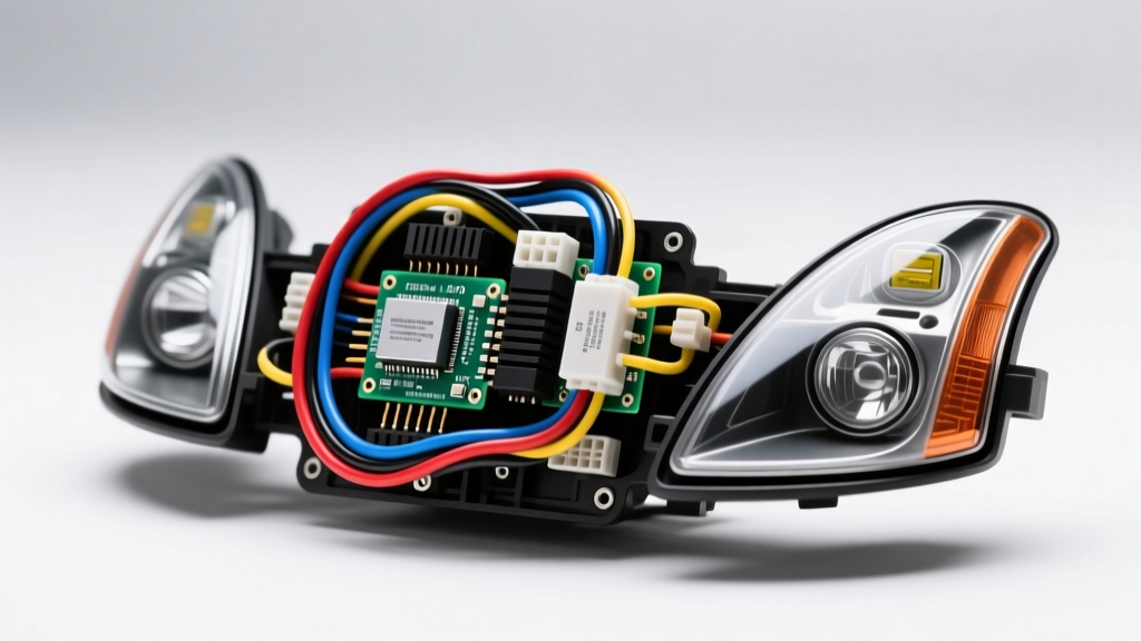
Understanding the Z33 Lighting Architecture
The 2006 Nissan 350Z (Z33 chassis) represents a pivotal year in Nissan’s electrical architecture, transitioning to a highly integrated multiplex network. Unlike older vehicles where the headlight switch directly routed 12V power to the bulbs, the 350Z utilizes a Body Control Module (BCM) and an Intelligent Power Distribution Module (IPDM). When you activate the headlight stalk, the BCM sends a low-voltage CAN-BUS signal to the IPDM, which then closes an internal high-current relay to send battery voltage to the headlights.
For the 2006 model year, the majority of Touring, Grand Touring, and Track trims came equipped with factory Bi-Xenon HID (High-Intensity Discharge) projectors. Understanding the 2006 Nissan 350Z headlights wiring diagram is absolutely critical before attempting any ballast replacements, LED retrofits, or projector swaps. Misinterpreting the IPDM outputs or the bi-xenon solenoid triggers can result in blown BCM traces, melted harnesses, or permanent IPDM failure.
2006 Nissan 350Z Headlights Wiring Diagram & Pinout
The factory headlight harness terminates at the rear of the headlight housing via a weather-sealed Sumitomo multi-pin connector. Below is the definitive pinout reference for the 2006 350Z factory HID (Bi-Xenon) setup. This data is cross-referenced with the Nissan Z33 Factory Service Manual Archives.
| Pin Number | Function | Wire Color (Typical) | AWG Size | Voltage / Signal |
|---|---|---|---|---|
| 1 | Main Chassis Ground | Black | 14 AWG | 0V (Ground) |
| 2 | Low Beam Power (HID Ballast) | Red/Yellow | 14 AWG | +12V (Switched via IPDM) |
| 3 | Bi-Xenon Shutter Solenoid (+) | Green/White | 18 AWG | +12V (High Beam Trigger) |
| 4 | Bi-Xenon Shutter Solenoid (-) | Black/White | 18 AWG | Ground (Switched) |
| 5 | Parking Light / DRL Signal | Red/Blue | 18 AWG | +12V (Switched via BCM) |
| 6 | Turn Signal Indicator | Light Green/Black | 16 AWG | +12V (Pulsed) |
Step-by-Step Headlight & Ballast Installation Guide
Whether you are replacing a burnt-out D2S bulb, installing a new OEM Mitsubishi ballast, or upgrading to an aftermarket LED projector retrofit, proper installation requires strict adherence to electrical safety and mechanical torque specifications.
Step 1: Bumper Cover and Headlight Housing Removal
- Open the hood and locate the 10mm bolts securing the top of the bumper cover to the radiator core support. Remove the plastic push-clips along the inner fender liners using a trim removal tool.
- From underneath the vehicle, remove the 10mm bolts securing the lower splash shield and the bumper-to-fender junction.
- Carefully pull the bumper cover outward from the fender tabs to unseat it, then rest it on a padded surface.
- Locate the three 10mm bolts securing the headlight housing to the chassis (two on top, one on the bottom bracket). Torque Spec Note: When reinstalling, these bolts must be torqued to exactly 5.5 Nm (48 in-lbs) to prevent stress fractures on the polycarbonate lens backing.
- Disconnect the main Sumitomo harness connector by depressing the release tab and pulling straight back.
Step 2: Wiring the HID Ballast and Igniter
The 2006 350Z uses a split ballast and igniter system. The ballast regulates the 35W continuous current, while the igniter steps up the voltage to 23,000V to strike the D2S xenon arc.
- Mounting: The OEM ballast is mounted to the bottom of the headlight housing using three T20 Torx screws. Ensure the rubber O-ring seal is properly seated to prevent moisture ingress, which is the leading cause of ballast corrosion on the Z33.
- Connections: Apply a thin layer of dielectric grease to the AMP/D2S connector pins before mating them to the bulb. A loose connection here will cause arcing, melting the connector and triggering a CAN-BUS error code in the BCM.
Step 3: Bi-Xenon Solenoid Shutter Integration
The 2006 350Z utilizes a single D2S bulb for both low and high beams. When you pull the turn signal stalk to the high-beam position, the IPDM sends +12V through the Green/White wire to a magnetic solenoid on the projector lens. This solenoid pulls a metal shield down, exposing the full beam pattern. If you are retrofitting aftermarket projectors (e.g., Morimoto Mini D2S), you must wire the aftermarket bi-xenon splitter harness directly to Pins 3 and 4. Do not use the high-beam auxiliary wire, as the 2006 HID trim does not utilize a separate H7 high-beam bulb.
The Z33 IPDM Low Beam Failure & Relay Bypass Mod
Any comprehensive guide on the 2006 Nissan 350Z headlights wiring diagram must address the notorious IPDM failure. While Nissan revised the IPDM in 2006 to handle higher inrush currents, installing aftermarket HID kits or high-draw LED bulbs without an external relay harness remains a massive risk.
The IPDM uses a surface-mounted PCB relay for the low beams. If an aftermarket ballast draws more than the factory 8A inrush spike, the microscopic copper traces on the IPDM circuit board will overheat and delaminate. Once this trace is broken, the low beams will never turn on again, requiring either a $400 IPDM replacement or advanced microsoldering to bridge the trace.
How to Wire an External Relay Bypass Harness
To protect your IPDM when upgrading lighting, install a heavy-duty 30A external relay harness. According to SAE J1124 Automotive Wiring Standards, bypassing multiplexed switching modules with discrete electromechanical relays ensures long-term circuit reliability.
- Tap into the factory Red/Yellow low beam wire (Pin 2) using a T-tap. This will serve as the low-current trigger signal for your external relay.
- Run a new 10 AWG power wire directly from the positive battery terminal to an inline 15A MAXI fuse holder, then to Pin 30 of a standard Bosch-style 5-pin relay.
- Connect Pin 87 of the relay to the +12V input of your aftermarket ballasts using 14 AWG primary wire.
- Ground Pin 85 of the relay to a clean, bare-metal chassis point near the radiator core support. Connect the factory trigger wire to Pin 86.
This configuration ensures the IPDM only handles the milliamp draw of the relay coil, completely isolating the high-current ballast startup surge from the Nissan multiplex network.
Wire Gauge and Terminal Specifications
When repairing damaged pigtails or extending harnesses for custom projector mounts, using the correct wire gauge and terminal crimps is vital. Refer to HID Planet Ballast Wiring Specifications for further insights on high-voltage automotive lighting.
| Circuit Type | Recommended AWG | Terminal Type | Max Current Draw |
|---|---|---|---|
| HID Ballast Power Feed | 14 AWG (Stranded Copper) | Sumitomo 250 Series Female | 10A Continuous |
| Bi-Xenon Solenoid Trigger | 18 AWG | Non-Insulated Spade / T-Tap | 2.5A Peak |
| External Relay Battery Feed | 10 AWG | Ring Terminal (1/4 inch stud) | 30A Fused |
| LED DRL / Parking Light | 20 AWG | Posi-Tap Connector | 0.5A Continuous |
Expert Troubleshooting: CAN-BUS Errors and Flickering
The 2006 350Z BCM actively monitors the voltage drop across the lighting circuits. If you replace the factory 35W HID ballasts with 55W aftermarket units, or switch to low-draw LED modules, the BCM will detect an anomaly. This usually results in the headlights flickering rapidly (PWM anti-flicker signaling) or the BCM shutting down the circuit entirely to prevent a perceived short.
The Fix: If installing LEDs, you must wire 50W 6-ohm load resistors in parallel with the low beam circuit. Mount the resistors to a bare metal section of the chassis or the aluminum headlight heat-sink using stainless steel self-tapping screws, as these resistors generate extreme heat (up to 300°F). Never zip-tie a load resistor to the factory wire loom, as it will melt the PVC insulation and cause a dead short to ground.
Final Assembly and Verification
Before reinstalling the front bumper cover, reconnect the battery and perform a full lighting diagnostic. Turn on the parking lights, verify the low beam ignition (which should take 3-5 seconds to reach full color temperature), and flash the high beams to listen for the distinct 'click' of the bi-xenon solenoids. Once verified, apply a bead of clear silicone RTV to the rear headlight access caps to ensure the housing remains sealed against moisture and road debris.