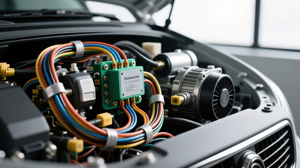
Deconstructing the Car Air Conditioner Electrical Diagram
Modern automotive climate control systems are no longer simple mechanical setups relying on a binary pressure switch and a manual Bowden cable. Today, interpreting a comprehensive car air conditioner electrical diagram requires a solid understanding of multiplexed networks, pulse-width modulation (PWM) blower controls, and PCM-managed compressor clutches or variable displacement swashplates. Whether you are diagnosing a no-blow condition, a shorted clutch coil, or a communication fault on the HVAC bus, the wiring schematic is your ultimate roadmap.
This complete walkthrough dissects the standard OEM wiring architecture found in most late-model domestic and import vehicles. We will focus on the electromagnetic clutch circuit, ISO relay logic, pressure transducer integration, and the blower motor control module. According to SAE International standards for automotive electrical diagnostics, understanding the distinction between the high-current load circuit and the low-current control circuit is the first step in isolating any A/C electrical fault.
The Load Circuit: Compressor Clutch and Coil Dynamics
The load side of the A/C diagram begins at the battery, passes through a high-amperage fuse (typically 15A to 20A for the clutch circuit), and feeds into the relay. From the relay, the power travels to the compressor clutch coil. The electromagnetic clutch coil is an inductive load with a typical cold resistance of 3.2 to 4.5 ohms. At a charging system voltage of 14.2 volts, the coil draws roughly 3 to 4 amps in a steady state, though inrush current can briefly spike higher.
OEM manufacturers typically use 14 AWG or 16 AWG primary wire for the clutch feed to minimize voltage drop over the distance from the underhood fuse block to the compressor. In GM applications, this wire is frequently Light Blue or Dark Green, while Ford often utilizes a Light Blue wire with a Red tracer. The connection at the compressor is almost universally a Metri-Pack 280 series weather-sealed connector, chosen for its ability to withstand high underhood temperatures and moisture ingress. The ground path for the clutch coil is usually completed locally at the compressor housing or engine block via a dedicated 14 AWG ground wire terminating in a ring terminal.
The Control Circuit: ISO Relay Logic and PCM Integration
The control side of the diagram dictates when the load circuit is energized. This is managed by a standard ISO mini relay, which acts as a bridge between the low-current PCM driver and the high-current clutch coil. The PCM utilizes a low-side driver, meaning it provides the ground path to energize the relay coil.
Below is the standard pinout and typical wire color reference for the A/C compressor relay found in most domestic and Asian wiring diagrams:
| Relay Pin | Function | Typical AWG | Common OEM Wire Color (GM/Ford) | Circuit Description |
|---|---|---|---|---|
| 30 | Load Power Feed (B+) | 12 - 14 AWG | Red / Orange | Constant battery power from the main A/C fuse. |
| 87 | Load Output (to Clutch) | 14 - 16 AWG | Light Blue / Dark Green | Switched power feeding the compressor clutch coil. |
| 86 | Coil Power Feed (B+) | 18 AWG | Pink / Light Green (Ignition) | Switched ignition power (RUN/CRANK) to energize the relay coil. |
| 85 | Coil Control Ground | 18 AWG | Dark Green/White / Yellow | Low-side driver ground path controlled directly by the PCM. |
When the PCM decides to engage the A/C, it grounds Pin 85. This completes the circuit for the relay's internal electromagnet, pulling the switch closed between Pins 30 and 87. Modern PCM drivers also monitor this circuit for voltage drop anomalies; if the PCM detects an open circuit (broken wire) or a short to ground on Pin 85, it will set a diagnostic trouble code (DTC) such as P0645 (A/C Clutch Relay Control Circuit) and disable the system to protect the driver transistor. For deeper relay testing methodologies, Haynes Technical Tutorials provides excellent visual guides on bench-testing ISO relays with a multimeter.
Sensor Inputs: Pressure Transducers and Evaporator Thermistors
The PCM will not ground the A/C relay unless it receives valid input data from the system's protection and regulation sensors. Older vehicles used binary or ternary pressure switches that simply opened or closed at specific PSI thresholds. Modern diagrams, however, feature a 3-wire A/C Pressure Transducer.
Pressure Transducer Wiring
- Pin A (5V Reference): Typically a Gray or Brown wire. Supplies a regulated 5 volts from the PCM.
- Pin B (Signal Return): Typically Light Blue or Dark Blue. Returns a variable voltage signal to the PCM based on refrigerant pressure (e.g., 0.5V at 0 psi, scaling linearly to 4.8V at 450+ psi).
- Pin C (Low Reference/Ground): Typically Black with a White tracer. Provides the dedicated sensor ground back to the PCM.
If the signal voltage drops below 0.4V (low refrigerant charge) or spikes above 4.9V (over-pressurization or an open signal circuit), the PCM will inhibit the A/C compressor relay to prevent catastrophic mechanical failure.
Evaporator Temperature Sensor
To prevent the evaporator core from freezing into a block of ice—which would halt airflow—the diagram includes an evaporator temperature sensor. This is a Negative Temperature Coefficient (NTC) thermistor. As the temperature drops, the sensor's resistance increases. A typical spec is 10,000 ohms at 25°C (77°F) and roughly 28,000 ohms at 0°C (32°F). When the PCM reads a voltage corresponding to roughly 34°F on the signal return wire, it will cycle the clutch relay off until the core warms up.
The Blower Motor Circuit: Resistor Packs vs. PWM Modules
A complete car air conditioner electrical diagram must also account for the cabin airflow. Base model vehicles utilize a blower motor resistor pack. This is a series of wire-wound resistors that drop voltage to achieve lower fan speeds. The wiring here is heavy-duty; the main blower feed is often 10 AWG or 12 AWG (usually Purple or Brown) to handle the 15+ amp draw of the blower motor on high speed. High speed bypasses the resistor pack entirely via a dedicated high-speed relay.
Higher-trim vehicles use a Blower Motor Control Module (BMC) utilizing Pulse Width Modulation. The BMC receives a PWM signal or a LIN bus data signal from the HVAC head unit. The wiring diagram for a PWM blower will show a heavy power and ground (10 AWG) for the motor, plus three small control wires (18-20 AWG): Battery Positive, Ground, and the PWM Control Signal. Diagnosing a no-blow condition on a PWM system requires an oscilloscope to verify the duty cycle of the control signal from the HVAC module, a technique heavily emphasized by Motor Age A/C Diagnostics.
Step-by-Step Diagnostic Walkthrough Using a Multimeter
When the A/C clutch fails to engage, follow this systematic electrical diagnostic path derived from OEM wiring diagrams:
- Verify Fuse Integrity: Do not just look at the fuse. Use a multimeter to check for battery voltage on both test points on the top of the A/C clutch fuse with the ignition ON.
- Test the Clutch Coil Resistance: Disconnect the Metri-Pack 280 connector at the compressor. Measure resistance across the coil terminals. A reading of 3.2 to 4.5 ohms is normal. A reading of OL (Open Line) indicates a burnt internal coil winding. A reading near 0.0 ohms indicates a short.
- Perform a Voltage Drop Test on the Load Circuit: With the engine running and A/C commanded ON (or jumpering the relay pins 30 and 87), place your red multimeter lead on the battery positive post and the black lead on Pin 87 of the relay socket. A voltage drop greater than 0.2V indicates high resistance (corrosion or broken strands) in the power feed.
- Verify PCM Control Ground: Connect a test light between battery positive and Pin 85 of the relay socket. Command the A/C ON. The test light should illuminate. If it does not, and all sensor inputs (pressure, evap temp) are within spec, the PCM driver may be faulty, or a CAN bus communication error exists between the HVAC head unit and the PCM.
Wiring Repair Standards and Best Practices
When repairing wires identified in the car air conditioner electrical diagram, never use 'scotch-lock' T-taps or twist connectors. The underhood environment is hostile, and vibration will quickly cause these to fail or corrode. Always cut out the damaged section and splice using sealed butt connectors with adhesive-lined heat shrink. For terminal replacements in the relay box or compressor connector, use the correct crimping tool for the specific terminal series (e.g., a Delphi Metri-Pack crimp tool). A proper mechanical crimp, followed by sealing the wire entry point with dielectric grease, ensures the repair will outlast the OEM wiring.