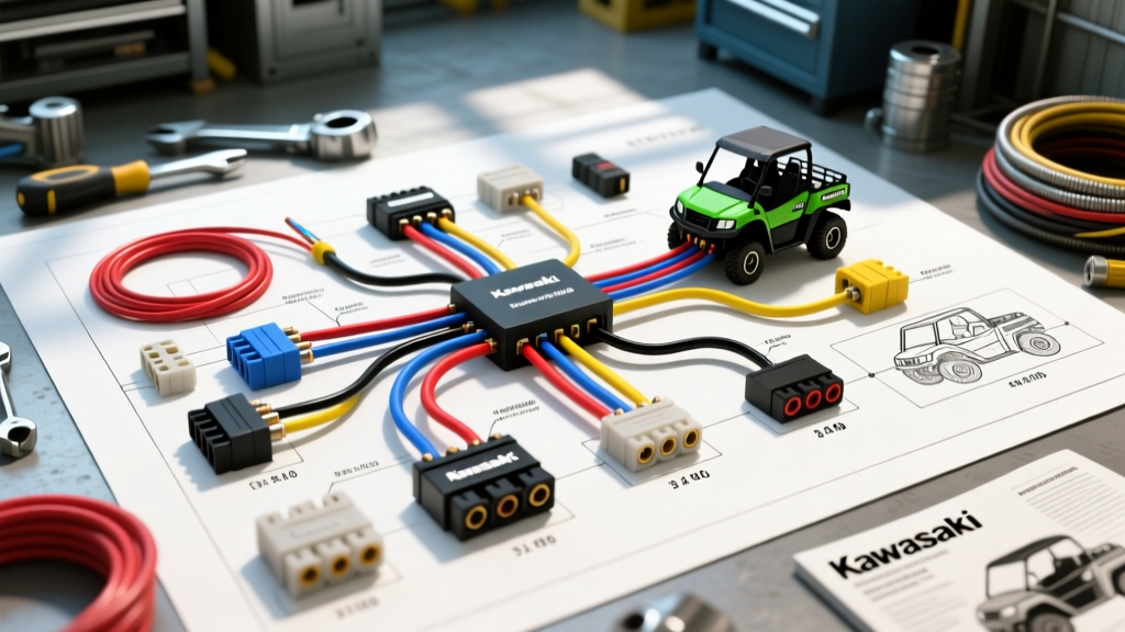
Decoding the Wiring Diagram for Kawasaki Mule 3010 UTVs
When diagnosing electrical faults on the 617cc V-twin Trans4x4 platform, securing an accurate wiring diagram for Kawasaki Mule 3010 models is only the first step. The true challenge lies in translating schematic logic into cost-effective, field-ready repairs. Unlike modern CAN-bus systems, the Mule 3010 relies on a traditional analog point-to-point architecture. This makes it highly serviceable, provided you understand the specific wire gauges, Sumitomo connector pinouts, and the hidden costs associated with OEM replacement parts versus custom loom fabrication.
Essential Diagnostic Tools & Budget Breakdown
Before cutting a single zip-tie, you must assemble a diagnostic toolkit capable of handling both low-amperage sensor circuits and high-amperage starter feeds. The Mule 3010's charging system and safety interlock modules require precise voltage and resistance measurements. Relying on a cheap multimeter will lead to misdiagnosed stators and unnecessary parts swapping.
| Tool Requirement | Specification / Model | Est. Cost | Application on Mule 3010 |
|---|---|---|---|
| Digital Multimeter | Fluke 87V (True RMS) | $250 - $280 | Testing 3-phase AC stator output and millivolt drops across the safety interlock switches. |
| Power Probe | Power Probe III | $450 - $500 | Injecting 12V to test starter solenoid engagement and fuel pump operation without back-probing. |
| Wire Crimper | Delphi/Sumitomo 090 Ratchet | $85 - $120 | Crimping OEM-style waterproof terminals for the regulator/rectifier and stator pigtails. |
| Soldering Station | Hakko FX888D | $110 - $130 | Sealing high-vibration splices in the engine bay where crimp-only connections fatigue. |
| Tone Generator | Fluke IntelliTone Pro | $180 - $220 | Tracing broken 18 AWG wires inside the dash harness without stripping the main loom tape. |
Total Initial Diagnostic Investment: $1,075 - $1,250. For professional UTV mechanics, this toolkit pays for itself after two major harness rebuilds.
Critical Circuit Analysis: Stator & Regulator/Rectifier
The most frequent and costly electrical failure on the Mule 3010 involves the charging system. According to Kawasaki Official Service Documentation, the stator generates 3-phase AC power which the Regulator/Rectifier (R/R) converts to DC. The wiring diagram highlights three Yellow wires (16 AWG) running from the stator to the R/R.
The Melted Connector Failure Mode
A common real-world failure is the melting of the OEM plastic connector between the stator and the R/R. The Mule 3010 generates significant heat in the rear engine casing. Over time, vibration and thermal cycling cause the female terminals in the plastic housing to lose tension. This increases electrical resistance, generating enough heat to melt the plastic and cause a short to ground or an open circuit.
- OEM Dealer Fix: Replace the entire stator assembly and main harness. Cost: $450+ in parts alone.
- Expert Auto-Electrician Fix: Cut out the melted connector. Solder and seal the three Yellow 16 AWG wires directly to the R/R using dual-wall adhesive heat shrink, or install a heavy-duty 50A-rated Deutsch DT connector. Cost: $12 in materials.
Stator & R/R Pinout and Testing Specifications
| Circuit | Wire Color | AWG | Test Parameter | Pass/Fail Threshold |
|---|---|---|---|---|
| Stator Phase 1, 2, 3 | Yellow (x3) | 16 | AC Voltage (Unloaded, 3000 RPM) | > 28V AC (Pass) / < 20V AC (Fail) |
| Stator Ground Isolation | Yellow to Engine Block | 16 | Resistance (Ohms) | OL / Infinite (Pass) / Any Continuity (Fail) |
| R/R Battery Feed | Red | 12 | Voltage Drop (Under Load) | < 0.2V Drop (Pass) |
| R/R Ground | Black/Yellow | 14 | Continuity to Frame | < 0.5 Ohms (Pass) |
| R/R Sense Wire | White | 18 | Battery Voltage at R/R Plug | Must match battery terminal voltage within 0.1V |
CDI, Ignition Coil, and Spark Plug Cap Diagnostics
The ignition system on the 617cc V-twin is driven by the CDI unit, which receives pulse signals from the pickup coil. The wiring diagram shows the pickup coil utilizing a White/Red wire for the signal and a Black/Yellow for ground. A frequent cause of no-spark conditions that is entirely unrelated to the CDI itself is the degradation of the spark plug caps. The OEM resistor caps are rated at 5,000 ohms. When moisture breaches the rubber boot, internal corrosion spikes the resistance well beyond 15,000 ohms, choking the spark under load. Always test the plug caps with your multimeter before condemning the $180 CDI unit or the $65 ignition coil. Furthermore, ensure the engine stop switch (tether switch) wiring—typically a Black/White wire routing to ground—is not frayed inside the steering column housing, as this will intermittently kill the ignition circuit.
Safety Interlock System: Bypass & Repair Costs
The Mule 3010 wiring diagram details a strict safety interlock system designed to prevent the engine from cranking unless the brake is depressed, the PTO is disengaged, and the transmission is in neutral. These switches route 18 AWG ground signals to the CDI and starter solenoid relay.
When a UTV is used in harsh agricultural environments, mud and moisture ingress corrode the micro-switches. Diagnosing which switch is interrupting the starter relay circuit requires back-probing the interlock module connectors. If the OEM interlock control box fails, dealerships often charge upwards of $280 for the replacement unit. However, using the schematic, an experienced technician can bypass the logic board by wiring a standard 30A Bosch-style relay to trigger the starter solenoid directly from the ignition switch's 'Start' position, provided the operator adheres to manual safety protocols. This custom relay bypass costs less than $8 in hardware.
OEM Harness vs. Custom Loom Cost Analysis
When rodent damage or severe chafing destroys the main harness, owners face a critical financial decision. The SAE J1128 Primary Cable Specifications dictate the thermal and chemical resistance required for engine bay wiring. Sourcing automotive-grade GXL (Cross-linked) wire is mandatory; using cheap PVC wire from a hardware store will result in melted insulation near the exhaust headers.
| Repair Strategy | Material Costs | Labor Time | Longevity & Reliability |
|---|---|---|---|
| Full OEM Harness Replacement | $350 - $550 | 6 - 8 Hours | Exact factory fit; requires complete dash and bed disassembly. |
| Targeted Splice Repair | $20 - $40 | 1 - 2 Hours | High risk of future failure if moisture seals are compromised. |
| Custom Loom Fabrication | $80 - $120 (Bulk GXL wire, Deutsch/Sumitomo terminals, braided loom) | 4 - 5 Hours | Superior to OEM if solder-sealed and routed with high-temp sleeving. |
Expert Workflow: Executing the Repair
- Isolate the Battery: Disconnect the negative 10 AWG ground cable. The Mule 3010's main fuse is located inline on the positive feed; verify it is intact before proceeding.
- Map the Schematic: Identify the specific circuit branch on the wiring diagram. Note the wire colors and the specific Sumitomo 090 series cavity numbers.
- Perform Voltage Drop Tests: Before replacing any component (like the $140 OEM R/R), test the wiring feeding it. A bad ground on the Black/Yellow wire will mimic a failed R/R.
- Execute Solder-Seal Splices: For any cut wires in the engine bay, strip the GXL insulation, twist the conductors, and apply rosin-core solder. Slide dual-wall polyolefin heat shrink over the joint and apply heat until the adhesive sealant purges from the edges.
- Secure and Route: Use nylon cable ties and flexible split-loom tubing to secure the harness away from the CVT intake and exhaust manifold. Maintain a minimum 3-inch clearance from all moving belts and hot exhaust components.
Mastering the electrical layout of the Mule 3010 transforms a frustrating diagnostic nightmare into a systematic, cost-saving procedure. By investing in the right crimping tools, understanding the exact AWG requirements, and knowing when to bypass expensive OEM assemblies with superior custom wiring, you ensure the UTV remains operational in the harshest environments.