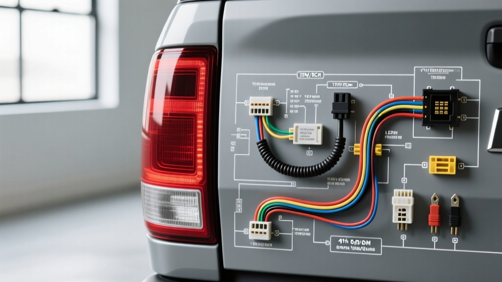
Decoding the 4th Gen Ram Tail Light Wiring Diagram
When tackling an exterior lighting overhaul on a 4th generation Ram (encompassing the 2009-2018 Ram 1500 and 2010-2024 Ram 2500/3500 Heavy Duty platforms), understanding the factory rear lighting architecture is critical. Unlike older Dodge trucks that relied on simple analog 12V switches, the 4th gen Ram utilizes a complex multiplexed network managed by either the Totally Integrated Power Module (TIPM) on early models or the Body Control Module (BCM) on 2013+ refreshed models. This 4th gen ram tail light wiring diagram guide provides the exact pinouts, wire color codes, and modification strategies required for LED swaps, sequential turn signal installations, and bed cap integrations without triggering dashboard CELs or hyperflash.
OEM Rear Harness Pinout & Wire Specifications
The main tail light harness on a 4th gen Ram terminates at the rear lamp housing via a Sumitomo 4-pin waterproof connector. The backup lamp circuit is typically routed through a separate 2-pin connector on the housing. Below is the standard Mopar pinout configuration for the primary stop/turn/tail harness. Always verify with a digital multimeter (DMM) before cutting, as mid-cycle manufacturing refreshes occasionally swapped tracer colors.
| Pin Cavity | Function | OEM Wire Color | Factory AWG | Operating Voltage |
|---|---|---|---|---|
| 1 | Left Stop / Turn Signal | Dark Green / White (DG/WT) | 18 AWG | 12.4V - 14.2V |
| 2 | Right Stop / Turn Signal | Dark Green / Orange (DG/OR) | 18 AWG | 12.4V - 14.2V |
| 3 | Park / Tail / Marker | White / Tan (WT/TN) | 18 AWG | 12.4V - 14.2V |
| 4 | Chassis Ground | Black (BK) | 16 AWG | 0.0V (Target < 0.1V drop) |
Source reference: Wiring schematics verified via Mopar TechAuthority diagnostic portals and standard SAE J1128 low-tension primary cable specifications.
The LED Upgrade Challenge: PWM & Hyperflash
The most common modification project for 4th gen Rams is swapping factory incandescent bulbs (typically 3157 or 4157 equivalents) for high-output LED assemblies. However, simply plugging in LEDs often results in a rapid "strobing" effect or hyperflashing. This is not a wiring fault; it is a feature of the Ram's Pulse Width Modulation (PWM) bulb-check system.
Why Standard LED Swaps Fail on 4th Gen Rams
When you turn on the ignition or activate a turn signal, the BCM/TIPM sends a rapid, low-voltage PWM pulse to the lighting circuit to measure resistance. If the module detects the high resistance of an incandescent filament, it opens the gate and sends a steady 12V+ current. Because LEDs draw a fraction of the amperage (often less than 0.5A compared to the factory 2.1A), the BCM interprets the circuit as "open" or a blown bulb. It will either cut power entirely, trigger a "Lamp Out" message on the EVIC (Electronic Vehicle Information Center), or rapidly cycle the PWM pulse, causing the LEDs to strobe violently.
Step-by-Step Modification: Integrating Load Resistors & Decoders
To successfully complete your LED tail light swap, you must trick the BCM into seeing an incandescent load. While plug-and-play CAN-bus decoders exist, hardwiring 50W 6-Ohm load resistors remains the most reliable, heat-dissipating method for heavy-duty truck applications subjected to vibration and moisture.
Sizing and Wiring the Load Resistors
- Component Selection: Use 50-Watt, 6-Ohm aluminum-housed resistors. Do not use lower wattage; the resistor must absorb the amperage difference between the LED and the OEM bulb safely.
- Tap the Signal Wire: Using an adhesive-lined heat shrink butt connector (avoid T-taps or Scotchloks, which invite corrosion), splice the resistor inline between the Turn/Stop signal wire (e.g., Pin 1 DG/WT) and the Ground wire (Pin 4 BK).
- Upgrade the Ground: The factory 18 AWG ground wire cannot safely handle the thermal load of the resistor. You must run a dedicated 14 AWG ground wire from the resistor's ground lug directly to a clean, bare-metal point on the truck frame. Use a stainless steel ring terminal and a self-tapping star washer to bite through the powder coating.
- Thermal Management: Mount the aluminum resistor body to the inner metal bed wall or frame rail using stainless steel hardware. Never zip-tie a resistor to the plastic bumper cover or the OEM wiring loom, as it will reach temperatures exceeding 250°F (121°C) during prolonged brake application.
Modification Project: Bed Cap & CHMSL Integration
Another frequent 4th gen Ram project is wiring a truck cap, canopy, or bed-mounted light bar. Tapping directly into the tail light harness for a bed cap's interior dome light or 3rd brake light (CHMSL) is a critical mistake that can fry the BCM. The BCM lighting drivers are rated for specific amperage thresholds; adding 10+ amps of bed lighting will melt the internal BCM traces.
Tapping the High-Mount Stop Lamp (CHMSL) Circuit
To wire a bed cap brake light safely, you must isolate the factory circuit using an automotive relay.
- Locate the CHMSL Feed: The CHMSL wire is typically found in the rear harness breakout near the spare tire winch, often colored Light Green/White (LG/WT) or White/Tan with a specific tracer depending on the exact model year.
- Wire the Relay: Use a standard Bosch-style 30A SPDT relay. Connect Terminal 85 to the OEM CHMSL wire (using a diode to prevent backfeed voltage spikes). Connect Terminal 86 to a solid chassis ground.
- Heavy Power Feed: Run a new 12 AWG power wire directly from the under-hood fuse box (using an Add-A-Circuit fuse tap on a switched ignition or battery-fed circuit, depending on your needs) to Relay Terminal 30.
- Output to Bed Cap: Run a 14 AWG wire from Relay Terminal 87 up through the bed rail grommet to your bed cap's 3rd brake light. This ensures the BCM only sees the 0.15A draw of the relay coil, completely protecting the factory 4th gen ram tail light wiring diagram integrity.
Troubleshooting Decision Tree: 4th Gen Lighting Faults
If your modification project results in erratic behavior, follow this diagnostic sequence before replacing expensive LED assemblies:
Symptom: One LED Tail Light Stays Dimly Lit When Truck is Off
- Cause: BCM "Keep Alive" voltage bleed or a poor ground causing backfeed through the filaments/LED drivers.
- Fix: Install a 1N4007 rectifier diode on the positive feed wire to block reverse polarity voltage bleed, or verify the ground ring terminal has less than 0.05 ohms of resistance to the negative battery terminal.
Symptom: Turn Signal Hyperflashes Only on One Side
- Cause: Unequal resistance. The BCM monitors left and right circuits independently.
- Fix: Verify the 50W 6-Ohm resistor on the affected side is not heat-damaged (measure with a DMM; it should read exactly 6.0 ohms). Check for corrosion inside the Sumitomo 4-pin housing; apply dielectric grease to the terminals.
Symptom: Entire Rear Lighting Cluster Flickers at Idle
- Cause: The infamous 4th Gen Ram "Bed Ground" corrosion issue. The main harness ground bolt near the rear crossmember corrodes, forcing return current through the license plate lamp or trailer harness grounds.
- Fix: Locate the main rear harness ground ring terminal bolted to the frame near the spare tire. Remove the bolt, sand the frame down to bare steel, apply zinc-rich cold galvanizing spray, and re-secure with a new Grade 8 flange bolt. Upgrade the ground pigtail to 12 AWG.
By respecting the multiplexed nature of the Ram's electrical system and utilizing proper gauge wire, relays, and thermal management, your lighting upgrades will be both DOT-compliant and electrically bulletproof. For further connector repair kits and terminal extraction tools, consult resources like the Mopar Repair Connection portal to ensure you are using OEM-spec Sumitomo terminals for any custom harness fabrication.