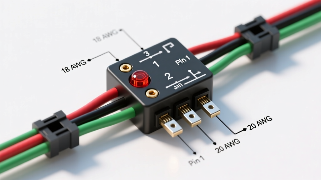
Anatomy of the 3-Pin Flasher Relay: Beyond the Basic Circuit
When diagnosing or upgrading classic and modern vehicle lighting systems, understanding the turn signal flasher 3 pin flasher relay wiring diagram is critical for maintaining SAE compliance and preventing electrical backfeed. Unlike a standard 2-pin flasher that simply interrupts power to the load, the 3-pin variant introduces a dedicated pilot circuit. This third terminal allows the dashboard indicator to operate independently of the exterior lighting circuit, a design staple in vintage General Motors, Ford, and JDM platforms.
Automotive electrical systems rely on standardized terminal designations to ensure uniformity across manufacturers. According to SAE J589 Turn Signal Lamps Standard and DIN 72552 protocols, the three terminals on a standard electromechanical flasher relay are designated as follows:
- B (Battery / 49): Constant 12V+ switched power feed from the ignition or hazard fuse.
- L (Load / 49a): Output to the turn signal switch and exterior lighting.
- P (Pilot / 31 or C0): Dedicated output to the dashboard turn indicator lamp.
Turn Signal Flasher 3 Pin Flasher Relay Wiring Diagram & Specifications
The physical routing of the wiring harness dictates the AWG (American Wire Gauge) requirements to prevent voltage drop and thermal degradation. The main load circuit must handle the combined amperage of front, rear, and side marker lamps, while the pilot circuit only services a low-draw dashboard bulb.
| Terminal | SAE / DIN ID | Typical OEM Wire Color | AWG Size | Circuit Function & Max Load |
|---|---|---|---|---|
| Power Feed | B / 49 | Purple or Red (12AWG) | 12 AWG | Fused 12V+ Ignition Source (15A Max) |
| Load Output | L / 49a | Brown or Light Green | 14 AWG | Turn Signal Switch Feed (12A Max) |
| Pilot Output | P / C0 | Dark Green / Light Blue | 18 AWG | Dashboard Indicator Lamp (2A Max) |
Circuit Routing and Harness Integration
The 'B' terminal receives power from the steering column fuse panel. In classic GM A-body vehicles, this is typically a 12 AWG purple wire originating from the 'DIR SIG' fuse. The 'L' terminal routes a 14 AWG wire directly to the multi-position turn signal switch located on the steering column. From the switch, the circuit splits into left (Dark Green) and right (Light Green) 16 AWG feeds to the exterior lamps. The 'P' terminal utilizes an 18 AWG wire that runs directly to the instrument cluster, bypassing the column switch entirely. This independent routing is what allows the dash indicator to flash even if an exterior bulb burns out, providing a crucial diagnostic layer for the driver.
Thermal vs. Electronic Solid-State Relays
To properly interpret a wiring schematic, you must identify whether the system utilizes a thermal bimetallic flasher or an electronic solid-state relay. MAD Electrical Technical Articles extensively documents the operational differences between these two architectures in classic vehicle restorations.
The Thermal Bimetallic Mechanism
Traditional 3-pin thermal flashers rely on a resistive heating element and a bimetallic strip. When the turn signal switch is engaged, current flows through the heating element. The resistance generates heat, causing the bimetallic strip to bend and break the contact points, extinguishing the lights. As the strip cools, it snaps back, reconnecting the circuit. This thermal cycle requires a minimum electrical load (typically 4.5 to 6 Amps) to generate sufficient heat. If a bulb burns out, the reduced amperage prevents the strip from heating, resulting in a solid 'on' state or an exceptionally slow flash rate.
Electronic Solid-State Architecture
Modern electronic 3-pin relays replace the thermal strip with an integrated circuit (IC) and a power MOSFET. These units flash at a precise, load-independent rate (usually 85 flashes per minute, per DOT regulations). Because they do not rely on thermal expansion, they will continue to flash even if only a single low-draw LED bulb is connected to the 'L' terminal. However, electronic relays are highly sensitive to reverse polarity and voltage spikes, requiring strict adherence to the B-L-P pinout configuration.
The LED Hyperflash Phenomenon and Load Resistor Math
Upgrading incandescent 1157 or 1156 bulbs to LEDs is the most common reason enthusiasts seek out the turn signal flasher 3 pin flasher relay wiring diagram. A standard incandescent 1157 bulb draws approximately 2.1 Amps on the high filament. A vehicle with two front and two rear turn signals pulls roughly 8.4 Amps. In contrast, a high-output LED equivalent draws only 0.15 to 0.25 Amps per lamp, dropping the total circuit load below 1 Amp.
When connected to a thermal relay, this lack of amperage triggers the 'hyperflash' protection mode—a deliberate SAE-mandated failure indicator designed to alert the driver to a burned-out bulb. To resolve this without replacing the flasher relay, you must introduce parallel load resistors to simulate incandescent amperage.
Calculating the 6-Ohm 50W Resistor
Using Ohm's Law (I = V / R), a standard 6-Ohm resistor on a 13.8V charging system draws 2.3 Amps (13.8 / 6 = 2.3). By wiring one 6-Ohm, 50-Watt resistor in parallel with each front LED bulb (between the Load wire and chassis Ground), you artificially restore the circuit amperage to the 4.5+ Amp threshold required by the thermal flasher. As noted by Daniel Stern Lighting Tech, load resistors must be mounted to a metal heat sink or chassis bracket, as they dissipate energy as extreme heat, capable of melting plastic wire looms if improperly secured.
Pilot Lamp Backfeed and Dash Indicator Anomalies
A frequent anomaly in 3-pin flasher circuits is 'sympathetic flashing' or backfeed, where the dashboard indicator glows dimly when the headlights are on, or flashes in opposition to the exterior lights. This occurs due to current leakage across the 'P' terminal or a poor ground at the instrument cluster.
In vehicles where the dashboard indicator shares a ground path with the headlight illumination circuit, a high-resistance ground forces the 12V+ signal from the 'P' terminal to seek an alternate path to ground through the headlight switch rheostat. The solution is not to replace the flasher, but to run a dedicated 16 AWG ground wire from the instrument cluster printed circuit board directly to the chassis, ensuring a zero-ohm return path.
Advanced Troubleshooting Decision Tree
When the turn signal system fails, use this structured diagnostic sequence to isolate the fault within the 3-pin circuit:
- Symptom: No exterior lights, no dash indicator, flasher is silent.
- Cause: Open circuit on the 'B' (Power) terminal.
- Test: Perform a voltage drop test between the battery positive post and the flasher 'B' spade. A reading above 0.1V indicates high resistance in the fuse panel or a corroded bulkhead connector.
- Symptom: Dash indicator flashes normally, but exterior lights do not illuminate.
- Cause: Open circuit on the 'L' (Load) terminal or failed turn signal switch.
- Test: Probe the 'L' terminal with a test light. If the test light flashes but the exterior lamps do not, the fault lies downstream in the steering column switch or the 14 AWG harness routing to the rear taillight pigtails.
- Symptom: Exterior lights flash normally, but dash indicator remains solid or is completely dead.
- Cause: 'P' (Pilot) terminal failure or instrument cluster ground fault.
- Test: Verify 12V pulsing at the 'P' spade. If present, the flasher is functional. The fault is isolated to the dashboard bulb filament, the cluster socket, or the aforementioned shared ground backfeed issue.
- Symptom: Flasher relay clicks rapidly (Hyperflash) immediately upon engagement.
- Cause: Insufficient circuit amperage (LED bulbs installed without resistors) or a burned-out exterior filament.
- Test: Clamp a DC ammeter around the 'L' wire. If total draw is below 3.5 Amps, the thermal strip cannot engage properly. Install 6-Ohm load resistors or swap to an electronic solid-state 3-pin LED flasher relay.
Summary of Best Practices
Executing a flawless installation based on the turn signal flasher 3 pin flasher relay wiring diagram requires more than just matching wire colors. It demands strict adherence to AWG sizing to prevent voltage drop across the steering column, proper thermal management for load resistors, and an understanding of how the independent pilot circuit interacts with the instrument cluster ground plane. By utilizing voltage drop testing rather than simple continuity checks, you can identify high-resistance corrosion in aging OEM spade connectors before they lead to catastrophic thermal melting of the fuse block.