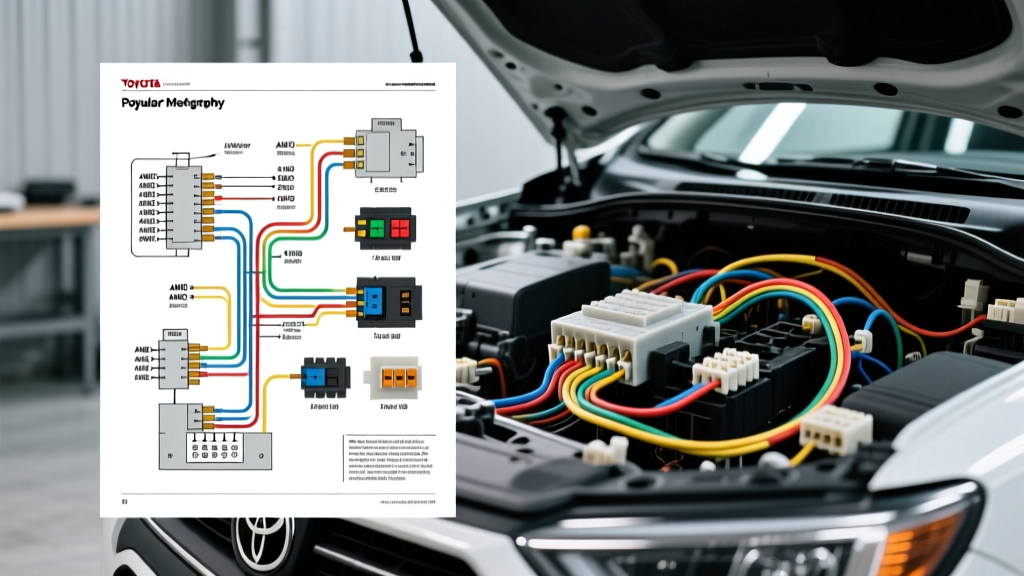
Why You Need a Factory Toyota RAV4 Wiring Diagram PDF for Overland Upgrades
The Toyota RAV4, particularly the Adventure and TRD Off-Road trims of the XA50 generation (2019-present), has become a staple in the overlanding and expedition community. However, transforming a stock crossover into a capable off-grid rig requires adding significant electrical loads: LED light bars, portable air compressors, winches, and dual-battery management systems. Modern Toyota vehicles rely heavily on multiplex communication networks (CAN-bus and LIN-bus) and solid-state switching. Splicing into the wrong harness without consulting a reliable Toyota RAV4 wiring diagram PDF can result in blown Body Control Modules (BCMs), parasitic battery drains, or catastrophic CAN-bus interference.
When planning an upgrade project, the factory service manual schematics are your most critical tool. Unlike generic aftermarket guides, the OEM wiring diagram PDF provides exact connector cavity pinouts, wire color codes (e.g., White/Black for ground, Gray for ignition-switched), and precise routing paths. This guide will walk you through executing high-current accessory upgrades safely, using factory relay blocks, proper AWG sizing, and automotive-grade termination techniques.
The Danger of CAN-Bus Interference in Modern RAV4s
Before cutting or tapping a single wire, you must understand the RAV4’s network topology. The XA50 RAV4 utilizes a high-speed CAN network (CAN-H and CAN-L) operating at 500 kbps to facilitate communication between the Engine Control Module (ECM), BCM, and Skid Control ECU. These twisted-pair wires are highly sensitive to resistance changes and electromagnetic interference (EMI).
If you attempt to trigger a high-draw accessory by back-probing a CAN-bus wire or tapping a multiplexed sensor circuit, you risk triggering U-codes (such as U0100 - Lost Communication with ECM/PCM). Always use the wiring diagram PDF to identify dedicated, non-multiplexed 12V sources and ignition-switched (IG1/IG2) trigger circuits. For auxiliary lighting, the safest method is to use an Add-A-Circuit fuse tap on a low-amperage IG1 fuse in the Engine Room Relay Block to trigger an isolated aftermarket relay.
Accessory Load Planning and AWG Sizing Chart
Proper wire gauge selection is non-negotiable for fire prevention and voltage efficiency. According to SAE J1128 standards for Low Tension Primary Cable, wire ampacity is heavily dependent on the insulation temperature rating and whether the wire is bundled or in free air. Under-hood environments in the RAV4 easily exceed 105°C near the exhaust manifold, requiring Cross-Linked Polyethylene (XLPE) or high-temp TXL wire rather than standard PVC.
| Accessory Component | Max Draw (Amps) | Recommended Wire Gauge (AWG) | Fuse Rating (Blade/ANL) | Connector Type |
|---|---|---|---|---|
| 50" LED Light Bar | 18A - 22A | 10 AWG TXL | 30A ATO Blade | Deutsch DT (2-Pin) |
| Portable Air Compressor | 30A - 45A (Surge) | 8 AWG SGX | 50A ANL / MIDI | Anderson Powerpole 50A |
| Relay Trigger (IG1 Tap) | 0.5A - 2A | 14 AWG GXL | 5A Mini Blade (Tap) | Sumitomo 090 (1-Pin) |
| Winch Control Solenoid | 15A (Control) | 12 AWG TXL | 20A ATO Blade | Weather-Pack (4-Pin) |
| Main Battery to Winch Feed | 300A+ (Peak) | 1/0 AWG Welding Cable | 250A ANL | Heavy Duty Ring Terminal |
Tapping the Engine Room Relay Block (XA50 Generation)
To ensure your auxiliary LED light bar or compressor only powers on when the ignition is in the "ON" position, you need a switched 12V trigger source. The RAV4’s under-hood fuse box (Engine Room Relay Block No. 1) contains several accessible circuits.
Step-by-Step: IG1 Relay Trigger Setup
- Locate the IG1 Fuse: Reference your Toyota RAV4 wiring diagram PDF to find the 10A IG1 (Ignition 1) or 10A ECU-IG1 fuse in the under-hood block. This circuit is hot only in the IGN and START positions.
- Install a Fuse Tap: Remove the factory 10A fuse. Insert it into the "original circuit" slot of an Add-A-Circuit fuse tap, and place a new 5A Mini fuse into the "accessory" slot. Reinsert the tap into the IG1 cavity.
- Run the Trigger Wire: Crimp a 14 AWG GXL wire to the tap's pigtail. Route this wire through the factory firewall grommet (located behind the main ECU harness, driver side) using a nylon fish tape. Apply silicone dielectric grease to the grommet to prevent tearing and water intrusion.
- Connect to the Aftermarket Relay: Terminate the 14 AWG wire to Pin 86 (Coil Positive) of a standard Bosch ISO mini relay. Connect Pin 85 (Coil Negative) to a dedicated chassis ground using a ring terminal and a star washer.
High-Current Routing: Winch and Compressor Feeds
For high-draw accessories like a hidden winch or a heavy-duty onboard air system, you must pull power directly from the battery or the main alternator stud. Never route 8 AWG or thicker cables through the cabin firewall unless absolutely necessary, as bending radius limitations can damage the copper stranding.
When routing 1/0 AWG or 8 AWG wire through the engine bay, use split-corrugated loom wrapped in Tesa 51036 PET fleece tape. Fleece tape prevents the loom from vibrating against the RAV4’s subframe and creating a rattling noise, while also providing superior abrasion resistance compared to standard vinyl electrical tape. Secure the harness every 6 inches using UV-resistant zip ties, maintaining at least 2 inches of clearance from the exhaust manifold and steering column intermediate shaft.
Sumitomo Connector Pinouts and Termination
Toyota relies heavily on Sumitomo and Yazaki connectors for under-hood sensor and actuator wiring. When integrating aftermarket sensors (like a dual-battery isolator monitor or a water-methanol injection kit) into the factory harness, do not use solder-and-tape methods. Solder creates a rigid stress point that will eventually fatigue and break due to engine vibration.
Instead, use Toyota Technical Information System (TIS) approved parallel crimp splices or, preferably, add a pigtail using the correct Sumitomo 090 series terminals. You will need a precision crimping tool (such as the TE Connectivity CERTI-CRIMP II) to achieve the proper bell-mouth crimp profile. A correct crimp ensures a gas-tight connection, preventing galvanic corrosion between the copper wire and the tin-plated brass terminal.
Grounding Best Practices: Avoiding the "Toyota Ground Gremlin"
The most common failure point in RAV4 modification projects is inadequate grounding. Toyota designates specific chassis ground points (e.g., G1A, G1B) which are often shared with critical ECU sensors. Overloading a factory ground point with a 30A LED light bar return can cause voltage backfeed, leading to flickering dash lights or erratic fuel trim readings.
The Fix: Create a dedicated ground bus bar mounted to the inner fender well or strut tower. Use 8 AWG wire to connect this bus bar directly to the negative battery terminal or the factory engine block ground stud. When attaching to the chassis, use a rotary file to remove all paint and clear coat down to bare metal. Treat the bare metal with a zinc-rich cold galvanizing spray to prevent rust, then secure the ring terminal with an M8 flange bolt and apply a dab of anti-corrosion grease over the exposed edges.
Troubleshooting Parasitic Draws Post-Modification
If your RAV4 battery is dying overnight after installing your auxiliary panel, you likely have a parasitic draw caused by an aftermarket relay failing to disengage, or a CAN-bus module being kept awake by a back-fed trigger wire.
Voltage Drop Testing the Fuse Block
Instead of pulling fuses one by one and waiting for the RAV4’s CAN-bus to go to sleep (which can take up to 45 minutes), use a digital multimeter to perform a voltage drop test across the fuses.
- Set your multimeter to the millivolt (mV) DC setting.
- With the vehicle fully asleep and the negative battery cable disconnected (with an ammeter in series reading the draw), place your multimeter probes on the two exposed test pads on the top of each Mini/ATO fuse.
- Consult a Pacer Group fuse voltage drop chart. Any fuse showing a significant millivolt reading is passing current. This instantly isolates the faulty aftermarket circuit without disturbing the sleep-state of the vehicle's computers.
Final Thoughts on RAV4 Electrical Upgrades
Upgrading the electrical system of a Toyota RAV4 for overland duty is highly rewarding, provided you respect the complexity of the factory wiring architecture. By leveraging a comprehensive Toyota RAV4 wiring diagram PDF, calculating your AWG requirements based on SAE standards, and utilizing proper automotive termination techniques, you will build a reliable, fire-safe, and trail-ready rig capable of handling the demands of off-grid exploration.