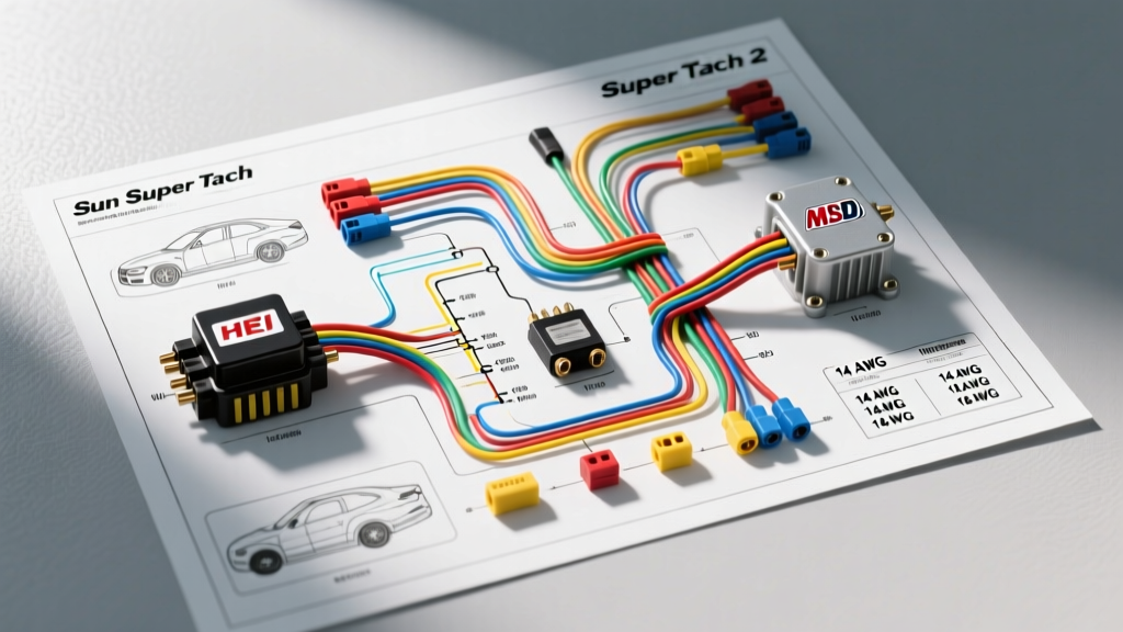
Introduction to the Sun Super Tach II Architecture
The Sun Super Tach II remains one of the most iconic analog tachometers in automotive history. Originally manufactured by Sun Electric Corporation, this gauge utilizes a precision air-core meter movement rather than the stepper motors found in modern digital gauges. While its vintage aesthetic is highly sought after for classic muscle cars, hot rods, and retro-mod builds, its internal analog circuitry requires a highly specific approach to signal integration. Unlike modern tachometers that feature microprocessors capable of auto-calibrating to various pulse widths and square waves, the Sun Super Tach II relies on reading the raw inductive kickback (voltage spike) from the ignition coil's primary winding or the raw trigger signal from an electronic ignition module.
Because of this analog reliance, installing this unit in modernized classic vehicles—especially those retrofitted with High Energy Ignition (HEI), Capacitive Discharge Ignition (CDI/MSD), or coil-on-plug (COP) systems—demands a thorough understanding of signal conditioning, impedance matching, and electromagnetic interference (EMI) mitigation. This advanced technical deep dive provides the definitive wiring diagram for Sun Super Tach 2 setups, detailing exact wire gauges, terminal specifications, and ignition-specific integration protocols.
Core Pinout and Wiring Diagram for Sun Super Tach 2
The foundational wiring diagram for Sun Super Tach 2 models utilizes a standardized 4-wire harness. To prevent voltage drop and signal degradation, strict adherence to SAE International J1141 Standards for automotive electrical assemblies is required. Do not use the factory 20 AWG wire lengths if the harness must be extended; instead, splice using solder and marine-grade adhesive-lined heat shrink to maintain circuit integrity.
| Terminal Label | Wire Color | Recommended AWG | Terminal Type | Circuit Function & Technical Notes |
|---|---|---|---|---|
| 12V+ | Red | 16 AWG | 0.187" Female Spade | Switched ignition power. Must be sourced from a dedicated 5A fused circuit. Avoid sharing with high-draw accessories to prevent voltage ripple. |
| GND | Black | 16 AWG | Ring Terminal (10-12) | Chassis ground. Must be secured to bare, unpainted metal. Maximum allowable resistance to battery negative is 0.05 ohms. |
| SIG | Green | 18 AWG | 0.187" Female Spade | Tachometer trigger signal. Connects to coil negative, HEI TACH terminal, or CDI adapter output. |
| LAMP | White | 18 AWG | 0.187" Female Spade | Dash illumination. Connect to headlight switch dimmer circuit (max 3A draw). |
Ignition System Specific Integrations
The green signal wire is the most critical component of the Sun Super Tach 2 wiring diagram. The method of sourcing this signal changes drastically depending on the ignition architecture managing the engine's spark events.
1. Breaker Points and Condenser Systems (Classic)
For traditional points-style ignitions, the green wire connects directly to the negative terminal of the ignition coil. When the points close, the primary circuit is grounded, and current builds in the coil. When the points open, the magnetic field collapses, inducing a high-voltage spike in the secondary winding (spark) and a lower-voltage inductive kickback (typically 150V to 250V) in the primary winding. The Sun tachometer's internal circuitry is designed to trigger off the falling edge of this primary spike. Critical Note: Ensure your ignition condenser (typically 0.20µF to 0.25µF) is in perfect condition. A failing condenser will cause severe arcing at the points, introducing high-frequency noise that will cause the tachometer needle to bounce erratically at idle.
2. GM HEI (High Energy Ignition) 4-Pin & 7-Pin Modules
GM HEI distributors feature a dedicated "TACH" terminal on the distributor cap. This terminal is internally buffered and protected by a carbon resistor (typically 5k ohms). Connect the green wire directly to this TACH terminal. Troubleshooting insight: If the tachometer reads zero or bounces violently on an HEI setup, the carbon resistor inside the distributor cap is likely cracked or degraded due to heat cycling and ozone exposure. Replacing the cap or bypassing the internal resistor by tapping the coil negative terminal directly inside the cap (requires careful fabrication) will resolve the issue.
3. CDI Systems (MSD 6-Series, Crane HI-6) and Signal Adapters
Capacitive Discharge Ignitions (CDI) like the MSD 6AL do not output a standard inductive kickback. Instead, they output a high-voltage square wave (up to 400V) and, below 3,000 RPM, fire multiple sparks per combustion event. Connecting the green wire directly to the negative terminal of an MSD Blaster coil will likely destroy the Sun Super Tach II's internal transistors or cause the needle to read 2x to 3x the actual RPM due to the multi-spark interpretation. According to MSD Performance Technical Bulletins, you must use a tachometer adapter (such as the MSD 8920) or tap the white "points trigger" wire on the MSD box, which provides a clean 12V square wave pulse that the Sun tachometer can safely process when paired with a pull-up resistor.
Advanced Signal Filtering and Noise Mitigation
Classic analog tachometers are highly susceptible to Electromagnetic Interference (EMI) and Radio Frequency Interference (RFI). If your Sun Super Tach II exhibits a rhythmic sweep or "whine" that correlates with engine RPM but reads higher than actual RPM, you are likely experiencing alternator diode ripple or ignition wire EMI.
- Alternator Ripple Filtering: If the 12V+ source is noisy, solder a 1000µF 25V electrolytic capacitor across the Red (12V+) and Black (Ground) wires as close to the tachometer housing as possible. This acts as a bulk reservoir to smooth out AC ripple from the alternator's rectifier diodes.
- Signal Line Snubber: To suppress high-frequency RFI induced into the green signal wire by solid-core spark plug wires or headers, solder a 0.1µF 50V ceramic disc capacitor between the Green (Signal) wire and the Black (Ground) wire. This creates a low-pass RC filter, shunting high-frequency noise to ground while allowing the low-frequency tachometer trigger pulses to pass unimpeded.
- Spark Plug Wires: Never use solid-core (metal) spark plug wires with a Sun Super Tach II. Always use carbon-core or spiral-core suppression wires (such as MSD Super Conductor 8.5mm) to prevent RFI radiation from the secondary ignition circuit from overwhelming the tachometer's analog amplifier.
Troubleshooting Decision Tree: Needle Bounce and Dead Tach
When diagnosing faults in the Sun Super Tach 2 wiring diagram, follow this structured diagnostic sequence based on Haynes Auto Electrical Manuals and vintage Sun Electric service protocols.
| Symptom | Root Cause Analysis | Technical Fix / Action Plan |
|---|---|---|
| Needle pegs at max RPM and stays there. | Open circuit on the green signal wire. The tachometer's internal pull-up resistor sees infinite resistance and defaults to maximum voltage interpretation. | Check continuity of the green wire from the tachometer terminal to the coil negative or TACH adapter. Verify spade connector tension. |
| Needle reads exactly 2x or 3x actual RPM. | Multi-spark CDI interpretation. The tachometer is counting every secondary spark pulse below 3,000 RPM as a separate combustion event. | Install an MSD 8920 Tach Adapter or re-trigger the tachometer off the primary ignition trigger signal (e.g., distributor magnetic pickup or white wire). |
| Needle bounces erratically at idle, stabilizes at high RPM. | Signal degradation due to high resistance in the ground circuit or failing ignition condenser/HEI cap resistor. | Voltage drop test the black ground wire (must be <0.05V). Replace ignition condenser or HEI distributor cap. |
| Tachometer is completely dead (no light, no movement). | Blown internal fuse, open 12V+ circuit, or failed internal voltage regulator. | Verify 12V+ at the red wire terminal with a multimeter. If power and ground are verified, the internal air-core driver IC has likely failed due to a voltage spike. |
Installation and Hardware Torque Specifications
The Sun Super Tach II housing is constructed from vintage ABS plastic and chromed bezels. When mounting the pedestal base to the steering column or dashboard, do not exceed 15 in-lbs of torque on the mounting hardware. Over-torquing the pedestal clamp will induce stress fractures in the ABS housing, leading to internal vibration that causes the needle to flutter mechanically, independent of the electrical signal. Use a split-lock washer and a flat washer to distribute the clamping load evenly across the pedestal base.
By adhering strictly to this wiring diagram for Sun Super Tach 2 configurations, utilizing the correct AWG wire sizes, and implementing proper signal conditioning for your specific ignition system, you will ensure dead-accurate RPM readings and preserve the longevity of this legendary piece of automotive instrumentation.