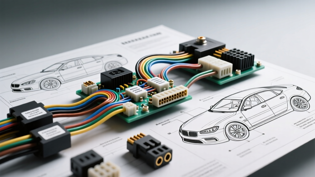
The Modifier’s Dilemma: Sourcing Accurate Schematics
When executing complex automotive modifications—whether you are dropping a Gen IV LS3 into a classic 1969 Camaro, retrofitting a modern CAN-bus steering column into a restomod, or upgrading a charging system to handle high-draw off-road lighting—guessing wire routes is a recipe for melted harnesses and fried control modules. Understanding how to get wiring diagrams for cars is the foundational first step of any successful upgrade project. Generic repair manuals often omit the detailed pinouts, splice pack locations, and ground distribution charts required for custom fabrication. This guide breaks down exactly where to source OEM-level schematics and how to translate those diagrams into physical, reliable harness modifications.
How to Get Wiring Diagrams for Cars: OEM vs. Aftermarket
For modification projects, the accuracy of your schematic dictates the success of your build. Aftermarket manuals (like Haynes or Chilton) are designed for basic component replacement, not harness fabrication or ECU repinning. To get the correct data, you must access Factory Service Manuals (FSM) or professional-grade databases.
Factory Service Manuals via Helm Incorporated
For Ford, GM, Honda, and Toyota applications, Helm Incorporated is the official publisher of OEM service manuals. Purchasing the specific year/model FSM provides you with the exact Power Distribution charts, Ground Distribution matrices, and Connector End-View diagrams. These diagrams show the exact cavity numbers, wire colors, and terminal types used on the assembly line, which is critical when you are building a custom merge harness for an engine swap.
Professional Databases (Alldata & Mitchell1)
If you are running a mod shop or tackling multiple projects, subscribing to AlldataDIY or Mitchell1 ProDemand gives you access to interactive wiring diagrams. These platforms allow you to trace circuits across multiple pages, view component location photos, and access Technical Service Bulletins (TSBs) that often detail factory wiring flaws you need to correct during your upgrade.
Decoding Connectors: Metri-Pack & Weather-Pack
Once you have your OEM diagrams, the next hurdle is physical integration. Modern vehicles rely heavily on sealed connector systems. When extending a harness for an engine setback plate or routing sensors through a custom firewall bulkhead, you must match the OEM connector series to maintain environmental sealing and prevent terminal fretting corrosion.
| Connector Series | Typical Application | Wire Gauge Range | Extraction Tool Part # |
|---|---|---|---|
| Aptiv Metri-Pack 150 | ECU Sensors, TPS, MAP, IAT | 18 - 22 AWG | Delphi 12094429 |
| Aptiv Metri-Pack 280 | Fuel Injectors, Idle Air Control | 12 - 16 AWG | Lisle 39950 |
| Weather-Pack (Sealed) | Headlights, Radiator Fans, Relays | 10 - 16 AWG | IWISS Weatherpack Tool |
| Deutsch DT Series | Aftermarket EFI, Transmission Solenoids | 14 - 20 AWG | Deutsch DT-EXT-01 |
Pro-Tip for Swaps: When repinning a GM LS PCM connector (such as the 80-way blue C1 connector), never use generic pick tools. The Metri-Pack 150 terminals feature a delicate primary and secondary lock (TPA). Using the incorrect Delphi extraction tool will bend the terminal tang, leading to a pushed-back pin and an intermittent 5V reference code (P0120) that is notoriously difficult to diagnose on the dyno.
Wire Selection: SAE J1128 Standards for Mods
Factory wiring diagrams specify wire colors and cross-sectional areas, but they do not always tell you what insulation type to buy for your custom harness. Standard hardware store THHN wire is too rigid and cannot withstand under-hood temperatures or the constant vibration of a motor mount. According to SAE J1128 standards, automotive wire must meet specific thermal and abrasion resistance criteria.
For custom modifications, always source TXL (Thin-wall Cross-linked) or GXL wire. TXL features a cross-linked polyethylene insulation that resists melting when routed near exhaust headers and handles continuous temperatures up to 125°C (257°F).
AWG Sizing Chart for Common Upgrade Circuits
| Circuit Type | Recommended AWG | Max Continuous Amps | Inline Fuse Rating |
|---|---|---|---|
| ECU Main Power / Ignition Switch | 12 AWG TXL | 25A | 30A ATO |
| High-Pressure Fuel Pump (e.g., Walbro 450) | 10 AWG TXL | 40A | 40A MIDI |
| Alternator Main Charge (Up to 150A) | 4 AWG SGX | 120A | 150A ANL |
| Wideband O2 Sensor Heater Ground | 16 AWG TXL | 10A | ECU Fused |
ECU Pinouts & CAN Bus Integration
When integrating a modern engine into an older chassis, the wiring diagram becomes your roadmap for bypassing factory immobilizers and integrating gauge clusters. For example, if you are wiring a 1998-2002 GM F-Body LS1 harness for a classic truck swap, the FSM will show that Pin 20 on the C2 (Red) connector is the Tachometer Output (Dark Green wire). Splicing this directly to an aftermarket AutoGauge tachometer requires a 1k-ohm pull-up resistor if the gauge expects a 12V square wave, whereas the PCM outputs a 5V pulse.
CAN Bus Twisted Pair Requirements
If your modification involves retaining the factory BCM (Body Control Module) or integrating a modern digital dash (like a Holley Terminator X or Dakota Digital RTX), you will be dealing with CAN bus networks. The wiring diagram will denote CAN-High and CAN-Low circuits.
- CAN-High: Typically White or Yellow (Idle 2.5V, Active 3.5V)
- CAN-Low: Typically Green or Black (Idle 2.5V, Active 1.5V)
Harness Looming & Environmental Protection
A wiring diagram only shows the electrical path; it does not show how to protect it. Once your custom harness is built and tested on the bench, it must be loomed correctly. Avoid using corrugated plastic split-loom tubing under the hood—it traps moisture, degrades under UV exposure, and looks unprofessional on a high-end build.
Instead, wrap your harness in Tesa 51036 PET cloth tape. This is the exact high-temperature harness tape used by OEM manufacturers like BMW and Ford. It provides excellent abrasion resistance against aluminum firewalls and valve covers, and it remains flexible in extreme heat. For any splices made during the modification, abandon electrical tape and solder. Use adhesive-lined heat shrink (such as 3M EPS300). When heated, the inner meltable adhesive flows into the wire strands, creating a completely waterproof, strain-relieved seal that prevents capillary action from drawing moisture into the copper strands.
Final Verification Before Power-Up
Before connecting the battery or uploading a custom tune, use your sourced wiring diagrams to perform a point-to-point continuity test with a digital multimeter. Verify that all ECU ground pins (often Black or Black/White stripes) read less than 0.2 ohms to the engine block. A poor ground on an O2 sensor reference circuit will cause the ECU to read a false lean condition, potentially leading to catastrophic engine detonation on the first startup. By combining OEM FSM data with SAE-compliant materials, your custom modification will be both electrically sound and factory-reliable.